
OMRON MY-GSRelays/ General Purpose Relays/For Control Panel
OMRON MY-GS Relays
OMRON MY-GS Dimensions
/Images/l_3440-25-265640-198x198.jpglast update: April 2, 2018
Easier to See, Easier to Use
OMRON insists on inhouse production from component molds to manufacturing facilities to better meet your needs.
Easily Accessible Information!
Product Information at a Glance
The model, specifications, and safety standards are all provided on the top surface.
You can check this information while the Relay is mounted in the Socket.

Contact Status at a Glance
Mechanical indicators are now a standard feature so that you know the contact operating status even for standard models.

Different Looks for Different Specifications
To prevent incorrectly using the Relays, we’ve made it easy to tell the difference between Relays with different specifications.

Added a Series with a Latching Lever that is Useful for Operation Check of Relay Sequence Circuits
Latching lever operating method

Note.According to the mechanism of the latching lever, the contacts are operated forcibly while the coil voltage is not
being applied.
Reliable Application!
High Durability
High Electrical Durability
Helps reduce the maintenance frequency.
Two-pole Relay: 500,000 operations
Four-pole Relay: 200,000 operations
Note. For switching the rated load. Refer to the datasheet for details.

Wide Ambient Operating Temperature
Reliable application is possible for high-density mounting and in cold locations.
Ambient operating temperature: -55 to 70°C

High Shock Resistance
Reduces malfunctions for unexpected external shocks.
Malfunction shock resistance: 20G

New Design Stable Quality in Automatic Manufacturing
We took 50 years of manufacturing experience and designed market needs into design and production.
Examples: Connection reliability was achieved with welding and one-piece molding while stable quality was achieved in automatic manufacturing.

last update: April 2, 2018
Purchase the OMRON For Control Panel Please fill in the following
If you have just landed here, this product OMRON MY-GS Relays,Relays is offered online by Tianin FLD Technical Co.,Ltd. This is an online store providing Relays at wholesale prices for consumers. You can call us or send enquiry, we would give you the prices, packing,deliverty and more detailed information on the MY-GS We cooperate with DHL,TNT,FEDEX,UPS,EMS,etc.They guarantee to meet your needs in terms of time and money,even if you need your OMRON MY-GSRelays tomorrow morning (aka overnight or next day air) on your desk, 2, 3 days or more.Note to international customers, YES, we ship worldwide.
D4F Small Safety Limit Switch/Features
Y92A-[][]N Watertight Cover/Features
D4CC Miniature Limit Switch/Features
ES1C Infrared Thermosensorc/Features
CJ1W-SPU01-V2 CJ-series High-speed Data Storage Unit (SPU Unit)/Features
OMRON MY-GS catalog
MY-GS Miniature Power Relays/Catalog- Catalog
English
Global Edition
| Catalog Name | Catalog Number [size] | Last Update | |
|---|---|---|---|
| | - [4052KB] | Apr 02, 201820180402 | MY-GS Data Sheet |
| | J196-E1-03 [1437KB] | Apr 02, 201820180402 | MY-GS Catalog |
OMRON MY-GS specification
MY-GS Miniature Power Relays/Specificationslast update: April 2, 2018
Ratings
Main unit
Operating Coil
| Item | Rated current (mA) | Coil resis- tance (Ω) | Coil inductance (H) | Must- operate voltage | Must- release voltage | Maxi- mum voltage | Power consumption (VA, W) | |||
|---|---|---|---|---|---|---|---|---|---|---|
| Rated voltage | 50 Hz | 60 Hz | Armature OFF | Armature ON | Percentage of rated voltage | |||||
| AC | 12 | 106.5 | 91 | 46 | 0.17 | 0.33 | 80% max. *1 | 30% min. *2 | 110% | Approx. 0.9 to 1.3 (at 60 Hz) |
| 24 | 53.8 | 46 | 180 | 0.69 | 1.3 | |||||
| 48 | 25.7 | 21.1 | 788 | 3.22 | 5.66 | |||||
| 100/110 | 11.7/12.9 | 10.0/11.0 | 3,750 | 14.54 | 24.6 | |||||
| 110/120 | 9.9/10.8 | 8.4/9.2 | 4,430 | 19.2 | 32.1 | |||||
| 200/220 | 6.2/6.8 | 5.3/5.8 | 12,950 | 54.75 | 94.07 | |||||
| 220/240 | 5.2/6.2 | 4.3/5.0 | 15,920 | 83.5 | 136.4 | |||||
| DC | 6 | 146 (151) | 41.0 (39.8) | 0.17 | 0.33 | 10% min. *2 | Approx. 0.9 | |||
| 12 | 72.7 (75) | 165 (160) | 0.73 | 1.37 | ||||||
| 24 | 36.3 (37.7) | 662 (636) | 3.2 | 5.72 | ||||||
| 48 | 17.6 (18.8) | 2,725 (2,560) | 10.6 | 21.0 | ||||||
| 100/110 | 8.7 (9.0)/9.6 (9.9) | 11,440 (11,100) | 45.6 | 86.2 | ||||||
| 220 | 3.6 | 60394 | 362.3 | 452.9 | Approx. 0.8 | |||||
Note:
1. The rated current and coil resistance are measured at a coil temperature of 23°C with tolerances of +15%/−20% for the AC rated current and +15% for the DC coil resistance.
2. The AC coil resistance and inductance values are reference values only (at 60 Hz).
3. Operating characteristics were measured at a coil temperature of 23°C.
4. The values in parentheses for the rated currents and coil voltages of DC coils are for models with LED operation indicators.
5. The maximum voltage capacity was measured at an ambient temperature of 23°C.
*1. There is variation between products, but actual values are 80% max.
The Relay will operate if 80% or higher of the rated voltage is applied. However, to achieve the specified characteristics, apply the rated voltage to the coil.
*2. There is variation between products, but actual values are 30% minimum for AC and 10% minimum for DC. To ensure release, use a value that is lower than the specified value.
Contacts
| 2 poles | 4 poles | |||
|---|---|---|---|---|
| Resistive load | Inductive load (cos φ = 0.4, L/R = 7 ms) | Resistive load | Inductive load (cos φ = 0.4, L/R = 7 ms) | |
| Contact configuration | DPDT | 4PDT | ||
| Contact structure | Single | |||
| Contact material | Ag | |||
| Rated load | 5 A at 220 VAC 5 A at 24 VDC | 2 A at 220 VAC 2 A at 24 VDC | 3 A at 220 VAC 3 A at 24 VDC | 0.8 A at 220 VAC 1.5 A at 24 VDC |
| Rated carry current | 5 A | 3 A | ||
| Maximum contact voltage | 250 VAC, 220 VDC | 250 VAC, 220 VDC | ||
| Maximum contact current | 5 A | 3 A | ||
| Maximum switching capacity | 1,100 VA 120 W | 440 VA 48 W | 660 VA 72 W | 176 VA 36 W |
| Minimum load (reference values)* | 1 mA at 5 VDC | |||
* These values are guides for the switchable limits for minute load levels, such as in electronic circuits. Actual characteristics may be different.
These values will depend on the switching frequency, atmosphere, and expected reliability level. Confirm applicability in the actual system under actual application conditions.
Characteristics
Main unit
| 2 poles | 4 poles | ||
|---|---|---|---|
| Contact resistance *1 | 100 mΩ max. | ||
| Operation time *2 | 20 ms max. | ||
| Release time *2 | 20 ms max. | ||
| Maximum operating frequency | Mechanical | 18, 000 operations/h | |
| Rated load | 2,400 operations/h | ||
| Insulation resistance *3 | 1,000 MΩ min. | ||
| Dielectric strength | Between coil and contacts | 2,000 VAC at 50/60 Hz for 1 min. | |
| Between contacts of different polarity | 2,000 VAC at 50/60 Hz for 1 min. | ||
| Between contacts of the same polarity | 1,000 VAC at 50/60 Hz for 1 min. | ||
| Vibration resistance | Destruction | 10 to 55 to 10 Hz, Double amplitude: 1.0 mm | |
| Malfunction | 10 to 55 to 10 Hz, Double amplitude: 1.0 mm | ||
| Shock resistance | Destruction | 1,000 m/s2 (approx. 100 G) | |
| Malfunction | 200 m/s2 (Approx. 20 G) | ||
| Endurance | Mechanical | 50,000,000 operations (switching frequency: 18,000 operations/h) | |
| Electrical *4 | 500,000 operations (switching frequency: 2,400 operations/h) | 200,000 operations (switching frequency: 2,400 operations/h) | |
| Ambient operating temperature | Standard models: -55 to 70°C (with no icing or condensation) Models with LED operation indicators: -40 to 70°C (with no icing or condensation) | ||
| Ambient humidity | 5% to 85% | ||
| Weight | Approx. 35 g | ||
Note: The above values are initial values.
*1. Measurement conditions: 1 A at 5 VDC using the voltage drop method.
*2. Measurement conditions: With rated operating power applied, not including contact bounce time.
*3. Measurement conditions: For 500 VDC applied to the same location as for dielectric strength measurement.
*4. Ambient temperature condition: 23°C Duty ratio: 33%
Options (order separately)
Sockets
| Model | Con- nec- tion | Num- ber of Pins | Ter- minal Type | Ambient operat- ing tem- pera- ture | Am- bient hu- midity | Con- tinuous carry current | Dielectric strength | Insu- lation re- sistance *1 | Weight | ||
|---|---|---|---|---|---|---|---|---|---|---|---|
| Between contact terminals of same polarity | Between contact terminals of different polarity | Between coil and contact terminals | |||||||||
| PYF08A-E | Front | 8 | Screw terminal | -55 to 70°C | 5% to 85% RH | 7A | 2,000 VAC 1 min | 2,000 VAC 1 min | 2,000 VAC 1 min | 1,000 MΩ min. (500 VDC) | Approx. 32 g |
| PYF08A-N | -55 to 70°C | 5% to 85% RH | 7A | 2,000 VAC 1 min | 2,000 VAC 1 min | 2,000 VAC 1 min | Approx. 32 g | ||||
| PYF-08-PU | Push-In Plus Terminal | -40 to 70°C | 10A *2 | 2,000 VAC 1 min | 2,000 VAC 1 min | 2,000 VAC 1 min | 1,000 MΩ min. (500 VDC) | Approx. 80 g | |||
| PYF14A-E | 14 | Screw terminal | -55 to 70°C | 5A | 2,000 VAC 1 min | 2,000 VAC 1 min | 2,000 VAC 1 min | 1,000 MΩ min. (500 VDC) | Approx. 50 g | ||
| PYF14A-N | -55 to 70°C | 5% to 85% RH | 5A | 2,000 VAC 1 min | 2,000 VAC 1 min | 2,000 VAC 1 min | Approx. 50 g | ||||
| PYF-14-PU | Push-In Plus Terminal | -40 to 70°C | 6A | 2,000 VAC 1 min | 2,000 VAC 1 min | 2,000 VAC 1 min | 1,000 MΩ min. (500 VDC) | Approx. 87 g | |||
| PY08-02 | Back | 8 | PCB terminals | -55 to 70°C | 5% to 85% RH | 7A | 1,500 VAC 1 min | 1,500 VAC 1 min | 1,500 VAC 1 min | 100 MΩ min. | Approx. 7.2 g |
| PY14-02 | 14 | -55 to 70°C | 5% to 85% RH | 3A | 1,500 VAC 1 min | 1,500 VAC 1 min | 1,500 VAC 1 min | 100 MΩ min. | Approx. 10 g | ||
*1. For 500 VDC applied to the same location as for dielectric strength measurement.
*2. The continuous carry current of 10 A is for an ambient temperature of 55°C. At an ambient temperature of 70°C, the
value is 7 A.
Socket Accessories
For front-connecting Sockets
Short Bars
| Application | Applicable sockets | Model | Maximum carry current | Ambient operating temperature | Ambient operating humidity |
|---|---|---|---|---|---|
| For Contact terminals (common) | PYF-08-PU(-L) PYF-14PU(-L) | PYDN-7.75-020[] | 20 A | -40 to 70°C | 5% to 85%RH |
| PYDN-7.75-030[] | |||||
| PYDN-7.75-040[] | |||||
| PYDN-7.75-200[] | |||||
| For Coil terminals | PYF-08-PU(-L) PYF-14PU(-L) | PYDN-31.0-080[] | 20 A | -40 to 70°C | 5% to 85%RH |
Certified Ratings for Models Certified for Safety Standards
The rated values for safety standard certification are not the same as individually defined performance values. Always check the specifications before use.
Main unit
UL-certified Models: UL508
| MY-GS | Number of poles | Coil ratings | Contact ratings | Certified number of operations |
|---|---|---|---|---|
| 2 | 12 VAC, 24 VAC, 48 VAC, 100/110 VAC, 110/120 VAC, 200/220 VAC, or 220/240 VAC 6 VDC, 12 VDC, 24 VDC, 48 VDC, 100/110 VDC, or 220 VDC | 5 A, 30 VDC (General Use) 5 A, 250 VAC (General Use) | 6,000 operations | |
| 4 | 12 VAC, 24 VAC, 48 VAC, 100/110 VAC, 110/120 VAC, 200/220 VAC, or 220/240 VAC 6 VDC, 12 VDC, 24 VDC, 48 VDC, 100/110 VDC, or 220 VDC | 3 A, 30 VDC (General Use) 3 A, 250 VAC (General Use) | 6,000 operations |
CSA-certified Models: CSA C22.2 No.14
| MY-GS | Number of poles | Coil ratings | Contact ratings | Certified number of operations |
|---|---|---|---|---|
| 2 | 12 VAC, 24 VAC, 48 VAC, 100/110 VAC, 110/120 VAC, 200/220 VAC, or 220/240 VAC 6 VDC, 12 VDC, 24 VDC, 48 VDC, 100/110 VDC, or 220 VDC | 5 A, 30 VDC (General Use) 5 A, 250 VAC (General Use) | 6,000 operations | |
| 4 | 12 VAC, 24 VAC, 48 VAC, 100/110 VAC, 110/120 VAC, 200/220 VAC, or 220/240 VAC 6 VDC, 12 VDC, 24 VDC, 48 VDC, 100/110 VDC, or 220 VDC | 3 A, 30 VDC (General Use) 3 A, 250 VAC (General Use) | 6,000 operations |
VDE-certified Models: EN 61810-1
| MY-GS | Number of poles | Coil ratings | Contact ratings | Certified number of operations |
|---|---|---|---|---|
| 2 | 12 VAC, 24 VAC, 48 VAC, 100/110 VAC, 110/120 VAC, 200/220 VAC, or 220/240 VAC 6 VDC, 12 VDC, 24 VDC, 48 VDC, 100/110 VDC, or 220 VDC | 5 A, 30 VDC (L/R = 1) 5 A, 250 VAC (cosφ = 1) | 10,000 operations | |
| 4 | 12 VAC, 24 VAC, 48 VAC, 100/110 VAC, 110/120 VAC, 200/220 VAC, or 220/240 VAC 6 VDC, 12 VDC, 24 VDC, 48 VDC, 100/110 VDC, or 220 VDC | 3 A, 30 VDC (L/R = 1) 3 A, 250 VAC (cosφ = 1) | 10,000 operations |
Options (order separately)
Sockets
CSA certified (File No. LR031928)
| Model | Ratings | Class number | Standard number |
|---|---|---|---|
| PYF08A-E | 7A 250V | 3211 07 | CSA C22.2 No14 |
| PYF14A-E | 7A 250V | ||
| PYF08A-N | 7A 250V | ||
| PYF14A-N | 7A 250V | ||
| PYF-08-PU | 10A 250V | ||
| PYF-14-PU | 6A 250V |
UL Standards Certification (File No. E87929)
| Model | Ratings | Standard number | Category | Listed/Recognized |
|---|---|---|---|---|
| PYF08A-E | 7A 250V | UL508 | SWIV2 | Recognized |
| PYF14A-E | ||||
| PYF08A-N | 7A 250V | |||
| PYF14A-N | ||||
| PYF-08-PU | 10A 250V | |||
| PYF-14-PU | 6A 250V |
TÜV Rheinland certification
| Model | Ratings | Standard number | Certification No. |
|---|---|---|---|
| PYF08A-N | 7A 250V | EN 61984 | J50224549 |
| PYF14A-N | |||
| PYF-08-PU | 10A 250V * | R50327595 | |
| PYF-14-PU | 6A 250V |
* Ratings are for an ambient temperature of up to 55°C. At an ambient temperature of 70°C, the value is 7A.
last update: April 2, 2018
OMRON MY-GS dimension
MY-GS Miniature Power Relays/Dimensionslast update: April 2, 2018
(Unit: mm)
Relays
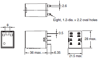
MY2-GS
MY2N-GS
MY2N-D2-GS
MY2N-CR-GS
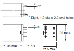
MY2IN-GS
MY2IN-D2-GS
MY2IN-CR-GS
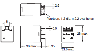
MY4-GS
MY4N-GS
MY4N-D2-GS
MY4N-CR-GS
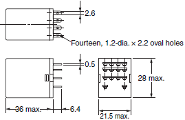
MY4IN-GS
MY4IN-D2-GS
MY4IN-CR-GS
Options (Order Separately)
Connection Sockets
Front-mounting Sockets
PYF08A-E
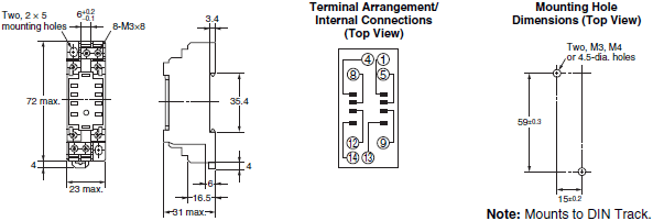
PYF14A-E
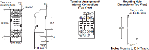
PYF08A-N
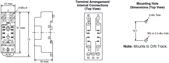
PYF14A-N
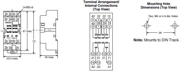
PYF-08-PU
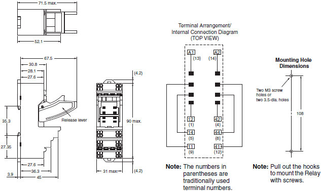
PYF-14-PU
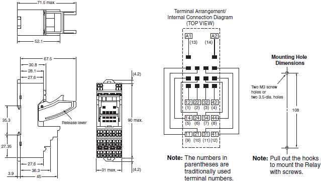
Back-mounting Sockets
PY08-02

PY14-02

Socket Accessories
Hold-down Clips
PYC-A1
Set of 2 clips
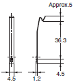
PYC-P
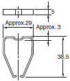
Mounting Heights with Sockets
Front-mounting Sockets

Back-mounting Sockets
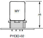
last update: April 2, 2018
OMRON MY-GS lineup
MY-GS Miniature Power Relays/Lineuplast update: April 2, 2018
List of Models
Miniature Power Relays (MY-GS)
| Category | Number of poles | Contact structure | Plug-in (octal pins) terminals | ||
|---|---|---|---|---|---|
| With operation indicator | |||||
| With latching lever | |||||
| Standard models | 2 | Single | MY2-GS | MY2N-GS | MY2IN-GS |
| 4 | MY4-GS | MY4N-GS | MY4IN-GS | ||
| Models with built-in diodes for coil surge absorption | 2 | --- | MY2N-D2-GS | MY2IN-D2-GS | |
| 4 | --- | MY4N-D2-GS | MY4IN-D2-GS | ||
| Models with built-in CR circuits for coil surge absorption | 2 | --- | MY2N-CR-GS | MY2IN-CR-GS | |
| 4 | --- | MY4N-CR-GS | MY4IN-CR-GS | ||
Ordering Information
Main unit
Standard model without operation indicator
| Number of poles | Model | Rated voltage (V) |
|---|---|---|
| 2 | MY2-GS | 12, 24, 100/110, 110/120, 200/220, 220/240 VAC 6, 12, 24, 48, 100/110 VDC |
| 4 | MY4-GS | 12, 24, 100/110, 110/120, 200/220, 220/240 VAC 6, 12, 24, 48, 100/110 VDC |
Standard model with operation indicator
| Number of poles | Model | Rated voltage (V) |
|---|---|---|
| 2 | MY2N-GS | 12, 24, 100/110, 110/120, 200/220, 220/240 VAC 6, 12, 24, 48, 100/110, 220 VDC |
| 4 | MY4N-GS | 12, 24, 100/110, 110/120, 200/220, 220/240 VAC 6, 12, 24, 48, 100/110, 220 VDC |
Standard model with operation indicator and latching lever
| Number of poles | Model | Rated voltage (V) |
|---|---|---|
| 2 | MY2IN-GS | 12, 24, 48, 100/110, 110/120, 200/220, 220/240 VAC 6, 12, 24, 48, 100/110, 220 VDC |
| 4 | MY4IN-GS | 12, 24, 48, 100/110, 110/120, 200/220, 220/240 VAC 6, 12, 24, 48, 100/110, 220 VDC |
Models with built-in diodes for coil surge absorption with operation indicator
| Number of poles | Model | Rated voltage (V) |
|---|---|---|
| 2 | MY2N-D2-GS | 12, 24, 48, 100/110, 220 VDC |
| 4 | MY4N-D2-GS | 12, 24, 48, 100/110, 220 VDC |
Models with built-in diodes for coil surge absorption with operation indicator and latching lever
| Number of poles | Model | Rated voltage (V) |
|---|---|---|
| 2 | MY2IN-D2-GS | 12, 24, 48, 100/110, 220 VDC |
| 4 | MY4IN-D2-GS | 12, 24, 48, 100/110, 220 VDC |
Models with built-in CR circuits for coil surge absorption with operation indicator
| Number of poles | Model | Rated voltage (V) |
|---|---|---|
| 2 | MY2N-CR-GS | 100/110, 110/120, 200/220, 220/240 VAC |
| 4 | MY4N-CR-GS | 100/110, 110/120, 200/220, 220/240 VAC |
Models with built-in CR circuits for coil surge absorption with operation indicator and latching lever
| Number of poles | Model | Rated voltage (V) |
|---|---|---|
| 2 | MY2IN-CR-GS | 100/110, 110/120, 200/220, 220/240 VAC |
| 4 | MY4IN-CR-GS | 100/110, 110/120, 200/220, 220/240 VAC |
Options (order separately)
Front-mounting Sockets
| Number of Pins | Applicable Relay Model | Terminal Type | Mounting Method | Appearance | Model | Hold-down Clips |
|---|---|---|---|---|---|---|
| 8 | MY2-GS MY2N-GS MY2IN-GS MY2N-D2-GS MY2IN-D2-GS MY2N-CR-GS MY2IN-CR-GS | Screw terminal Finger protection structure *1 (Screw size M3) | DIN Track or screw mounting |  | PYF08A-E | PYC-A1 *3 |
| Screw terminal Finger protection structure *1 (Screw size M3) | DIN Track or screw mounting |  | PYF08A-N | PYC-A1 *3 | ||
| Push-In Plus Terminal (Integrated Socket with release lever) | DIN Track or screw mounting *2 |  | PYF-08-PU | --- | ||
| 14 | MY4-GS MY4N-GS MY4IN-GS MY4N-D2-GS MY4IN-D2-GS MY4N-CR-GS MY4IN-CR-GS | Screw terminal Finger protection structure *1 (Screw size M3) | DIN Track or screw mounting |  | PYF14A-E | PYC-A1 *3 |
| Screw terminal Finger protection structure *1 (Screw size M3) | DIN Track or screw mounting |  | PYF14A-N | PYC-A1 *3 | ||
| Push-In Plus Terminal (Integrated Socket with release lever) | DIN Track or screw mounting *2 |  | PYF-14-PU | --- |
*1. In the finger protection type (PYF[]A-E and PYF[]A-N), the terminal cover is integrated into the Socket. Round terminals
cannot be used.
Use forked terminals or ferrules instead.
*2. There are screw mounting holes in the DIN hooks on the PYF-[][]-PU. Pull out the DIN hook tabs to mount the Sockets
with screws.
*3. Model number of the applicable Mounting Bracket. Sold in sets of two.
Back-mounting Sockets
| Number of Pins | Applicable Relay Model | Terminal Type | Appearance | Model | Hold-down Clips |
|---|---|---|---|---|---|
| 8 | PY08-02 | PCB terminals |  | PY08-02 | PYC-P |
| 14 | PY14-02 | PCB terminals |  | PY14-02 |
Socket accessories
Mounting Bracket
| Appearance *1 | Model | Weight *2 | Application |
|---|---|---|---|
 | PYC-A1 | Approx. 0.54 g | For joining the Socket and Relay |
 | PYC-P | Approx. 1.4 g | For joining the Socket and Relay |
*1. Describes the appearance when the Relay, Socket, and Mounting Bracket have been combined together.
*2. The PYC-A1 includes two Mounting Brackets in one set. The weight specified above is the weight of one Mounting
Bracket.
last update: April 2, 2018
- NO. MY-GS
- TYPE:General Purpose Relays For Control Panel
 Copyright Statement
 - DATE:2021-06-09
- Associated products:
G9SA-300-SC Safety Relay Unit (Sensor Connector Type)/Features G2RV-SR Slim I/O Relay/Features