
OMRON E5ED / E5ED-BControl Components/ Temperature Controllers/General-purpose
OMRON E5ED / E5ED-B Control Components
- E5ED / E5ED-B Digital Temperature Controller (48 x 96 mm)/Specifications
- E5ED / E5ED-B Digital Temperature Controller (48 x 96 mm)/Dimensions
- E5ED / E5ED-B Digital Temperature Controller (48 x 96 mm)/Catalog
- E5ED / E5ED-B Digital Temperature Controller (48 x 96 mm)/Lineup
- Purchase the OMRON E5ED / E5ED-B General-purpose
OMRON E5ED / E5ED-B Dimensions
/Images/l_3669-25-274684-198x198.jpglast update: January 5, 2018
The adjustments made by skilled workers are automated using AI. The innovation of production sites has begun.
Optimal and automatic temperature control without human intervention easily achieves both productivity and quality.
Previous temperature controllers have not only required a long time for start-up settings and variation adjustments, it has also been difficult to make the optimal adjustments without having experience and intuition. There were therefore some effects on quality.
In response to this situation, OMRON developed temperature controllers that includes "adaptive control technology."
This makes it possible to detect the changes in the status which will have an effect on quality and to automatically control the temperature so that the optimal state is always maintained, in the same way as a skilled worker would.
This frees production sites from troublesome start-up and adjustment work.
Causes of temperature variations on production lines

The answer was the industry's first inclusion* of "adaptive control technology"
With the "adaptive control" incorporated into this product, the optimal PID value is calculated automatically for both the time of the start-up and for during stable production. Furthermore, it is possible to monitor the temperature control status of the machine to automatically adjust the PID value to obtain the optimal temperature control in response to changes such as workpiece changes and machine changes.

* According to an investigation by OMRON of general-purpose temperature controllers for FA as of March 2017.
[New value that supports advances in packaging machines] The sealing temperature is measured accurately and controlled automatically for packaging machines that can maintain quality even at higher speeds.
Issues at production sites
· Faster packaging to respond to the demand for foodstuffs arising due to the population increases in emerging nations
· Increase in speed even when performing multiple-product production using a wide variety of packaging materials
· At higher speeds, the temperature difference between the sealing surface and the control temperature widens, so the failure rate rises…

E5[]D/NX-TC solve the issues
The temperature of the sealing surface is stably controlled automatically with measurement of the sealing surface temperature and algorithms to suppress variations.
Even if the speed of the packaging process is increased, the difference between the sealing temperature and the control temperature is minimized to perform stable automatic control, so it is possible to realize faster production while maintaining the product quality.
This also contributes to the use of thinner packaging materials and to high precision control.
Even with the production of multiple products that require changes to the settings, automatic control reduces the work
Even in the production of multiple products, which hinders faster speeds because a change of packaging materials can mean that time is required to change the settings, the use of automatic control that has a small error in the sealing temperature enables a speedy response at production sites.
Control performance that achieves new value
The temperature error is minimized with a temperature sensor for packaging machines* and an algorithm for packaging machines (automatic filter adjustment function)
*Sold separately
"Temperature sensors for packaging machines" to measure the temperature of the sealing surface
The temperature of the heating bar surface is measured accurately and there is no effect from factors causing temperature variations, such as the speed of the packaging machine and changes to the packaging materials.

"Automatic filter adjustment function" to suppress the instability in surface temperature measurements
By using the temperature sensor for packaging machines and the automatic filter adjustment function, it becomes possible to control the quality with the sealing temperature while also suppressing variation in the temperature with just a temperature controller, without relying on adjustments by workers.

[New value that supports advances in molding machines] Stable control of the temperature changes arising from faster speeds is performed automatically to realize molding machines that can maximize production capacity.
Issues at production sites
· Increased productivity to respond to demand expansion related to infrastructure as a result of the economic development of the emerging nations and the transfer of production bases overseas.
· At higher speeds, adjustments by the workers become necessary to respond to temperature variations arising due to factors such as the materials compounding and cooling water…
· It is difficult to achieve high speed production while also maintaining the quality…

E5[]D/NX-TC solve the issues
Temperature variations due to speed changes and changes in the status of machines are suppressed without adjustments by the workers
Stable control is achieved automatically by detecting the temperature variations on the heat generating parts of the material that occur when the speed of the extrusion molding machine is increased and by detecting the temperature variations due to variation in the cooling water. The work required for setting are also greatly reduced.
Also saves energy on the machine
The stable control reduces the wasteful use of energy on the heater by up to 40% compared with conventional machines.
* Data measured by OMRON on a water-cooled twin screw extrusion molding machine.
Control performance that achieves new value
Temperature variations are minimized with an algorithm for molding machines (water-cooling output adjustment function)
On a water-cooled extrusion molding machine, increased speed leads to temperature variations due to various causes and it was previously necessary for the workers to repeatedly make valve adjustments to stabilize the quality.
With the E5[]D/NX-TC, the water-cooling output adjustment function suppresses the temperature variations to a minimum and raises the production capacity with the quality maintained.

"Water-cooling output adjustment function" to simultaneously suppress the causes of temperature variations and maintain stable performance

Push-In Plus Technology for Easy Wiring
E5[]D-B/NX-TC
Just Insert Wires: No Tools Required
Now you can use Push-In Plus technology to reduce the time and work involved in wiring.
Greatly Reduce Wiring Work

*Information for Push-In Plus and screw terminal blocks is based on OMRON's actual measurement value data.
Easy to Insert
OMRON’s Push-In Plus technology are as easy as inserting to an earphone jack. They help reduce the work load and improve wiring quality.


Our shared Value Design for Panel (herein after referred to as "Value Design") concept for the specifications of products used in control panels will create new value to our customer’s control panels.
last update: January 5, 2018
Purchase the OMRON General-purpose Please fill in the following
If you have just landed here, this product OMRON E5ED / E5ED-B Control Components,Control Components is offered online by Tianin FLD Technical Co.,Ltd. This is an online store providing Control Components at wholesale prices for consumers. You can call us or send enquiry, we would give you the prices, packing,deliverty and more detailed information on the E5ED / E5ED-B We cooperate with DHL,TNT,FEDEX,UPS,EMS,etc.They guarantee to meet your needs in terms of time and money,even if you need your OMRON E5ED / E5ED-BControl Components tomorrow morning (aka overnight or next day air) on your desk, 2, 3 days or more.Note to international customers, YES, we ship worldwide.
E3X-HD Smart Fiber Sensor/Features
CJ1 CJ1 Overview/Features
GRT1-DRT DeviceNet Communications Unit/Features
ZN-THS-S / THX11-S Precision Thermo-Humidity Logger/Features
XW2B (Standard-type) Standard-type Connector-Terminal Block Conversion Units/Features
OMRON E5ED / E5ED-B specification
E5ED / E5ED-B Digital Temperature Controller (48 x 96 mm)/Specificationslast update: April 2, 2018
Ratings
| Power supply voltage | A in model number: 100 to 240 VAC, 50/60 Hz D in model number: 24 VAC, 50/60 Hz; 24 VDC | |
|---|---|---|
| Operating voltage range | 85% to 110% of rated supply voltage | |
| Power consumption | Models with option selection of 000: 6.6 VA max. at 100 to 240 VAC, and 4.1 VA max. at 24 VAC or 2.3 W max. at 24 VDC All other models: 8.3 VA max. at 100 to 240 VAC, and 5.5 VA max. at 24 VAC or 3.2 W max. at 24 VDC | |
| Sensor input | Temperature input Thermocouple: K, J, T, E, L, U, N, R, S, B, C/W, or PL II Platinum resistance thermometer: Pt100 or JPt100 Infrared temperature sensor (ES1B): 10 to 70°C, 60 to 120°C, 115 to 165°C, or 140 to 260°C Analog input Current input:4 to 20 mA or 0 to 20 mA Voltage input:1 to 5 V, 0 to 5 V, or 0 to 10 V | |
| Input impedance | Current input: 150 Ω max., Voltage input: 1 MΩ min. (Use a 1:1 connection when connecting the ES2-HB-N/THB-N.) | |
| Control method | ON/OFF control or 2-PID control (with auto-tuning) | |
| Control output | Relay output | SPST-NO, 250 VAC, 5 A (resistive load), electrical life: 100,000 operations, minimum applicable load: 5 V, 10 mA (reference value) |
| Voltage output (for driving SSR) | Output voltage: 12 VDC ±20% (PNP), max. load current: 40 mA, with short-circuit protection circuit (The maximum load current is 21 mA for models with two control outputs.) | |
| Linear current output | 4 to 20 or 0 to 20 mA DC, Load: 500 Ω max., Resolution: Approx. 10,000 | |
| Auxiliary output | Number of outputs | 4 |
| Output specifications | SPST-NO relay outputs, 250 VAC, 2 A (resistive load) Electrical life: 100,000 operations, Minimum applicable load: 10 mA at 5 V (reference values) | |
| Event input | Number of inputs | 2 or 4 (depends on model) |
| External contact input specifications | Contact input: ON: 1 kΩ max., OFF: 100 kΩ min. | |
| Non-contact input: ON: Residual voltage: 1.5 V max., OFF: Leakage current: 0.1 mA max. | ||
| Current flow: Approx. 7 mA per contact | ||
| Transfer Output | Number of outputs | 1 (depends on model): Transfer output type |
| Output specifications | Current output: 4 to 20 mA DC, Load: 500 Ω, Resolution: Approx. 10,000 Linear voltage output: 1 to 5 V DC, Load: 1 kΩ min., Resolution: Approx. 10,000 | |
| Setting method | Digital setting using front panel keys | |
| Indication method | 11-segment digital display, individual indicators, and bar display Character height: PV: 18.0 mm, SV: 11.0 mm, MV: 7.8 mm Three displays Contents: PV/SV/MV, PV/SV/Multi-SP, PV/SV/Remaining soak time, etc. Numbers of digits: 4 digits each for PV, SV, and MV displays | |
| Multi SP | Up to eight set points (SP0 to SP7) can be saved and selected using the event inputs, key operations, or serial communications. | |
| Bank switching | None | |
| Other functions | Adaptive control, automatic filter adjustment, water-cooling output adjustment, indication data (power ON time monitor, ambient temperature monitor, and control output ON/OFF count monitors), parameter masking, operation afte power ON, manual output, heating/cooling control, loop burnout alarm, SP ramp, other alarm functions, heater burnout (HB) alarm (including SSR failure (HS) alarm), 40% AT, 100% AT, MV limiter, input digital filter, robust tuning, PV input shift, run/stop, protection functions, extraction of square root, MV change rate limit, logic operations,temperature status display, simple programming, moving average of input value, and display brightness setting | |
| Ambient operating temperature | -10 to 55°C (with no condensation or icing), For 3-year warranty: -10 to 50°C with standard mounting (with no condensation or icing) | |
| Ambient operating humidity | 25% to 85% | |
| Storage temperature | -25 to 65°C (with no condensation or icing) | |
| Altitude | 2,000 m max. | |
| Recommended fuse | T2A, 250 VAC, time-lag, low-breaking capacity | |
| Installation environment | Overvoltage category II, Pollution Degree 2 (EN/IEC/UL 61010-1) | |
Input Ranges
Thermocouple/Platinum Resistance Thermometer (Universal inputs)
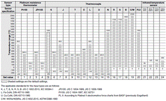
Analog input
| Input type | Current | Voltage | |||
|---|---|---|---|---|---|
| Input specification | 4 to 20 mA | 0 to 20 mA | 1 to 5 V | 0 to 5 V | 0 to 10 V |
| Setting range | Usable in the following ranges by scaling: -1999 to 9999, -199.9 to 999.9, -19.99 to 99.99 or -1.999 to 9.999 | ||||
| Set value | 25 | 26 | 27 | 28 | 29 |
Alarm Types
Each alarm can be independently set to one of the following 17 alarm types. The default is 2: Upper limit. (see note.)
Auxiliary outputs are allocated for alarms. ON delays and OFF delays (0 to 999 s) can also be specified.
Note:In the default settings for models with HB or HS alarms, alarm 1 is set to a heater alarm (HA) and the Alarm Type 1 parameter is not displayed.
To use alarm 1, set the output assignment to alarm 1.
| Set value | Alarm type | Alarm output operation | Description of function | |
|---|---|---|---|---|
| When alarm value X is positive | When alarm value X is negative | |||
| 0 | Alarm function OFF | Output OFF | No alarm | |
| 1 | Upper- and lower-limit *1 |  | *2 | Set the upward deviation in the set point for the alarm upper limit (H) and the lower deviation in the set point for the alarm lower limit (L). The alarm is ON when the PV is outside this deviation range. |
| 2 (default) | Upper-limit |  |  | Set the upward deviation in the set point by setting the alarm value (X). The alarm is ON when the PV is higher than the SP by the deviation or more. |
| 3 | Lower-limit |  |  | Set the downward deviation in the set point by setting the alarm value (X). The alarm is ON when the PV is lower than the SP by the deviation or more. |
| 4 | Upper- and lower-limit range *1 |  | *3 | Set the upward deviation in the set point for the alarm upper limit (H) and the lower deviation in the set point for the alarm lower limit (L). The alarm is ON when the PV is inside this deviation range. |
| 5 | Upper- and lower-limit with standby sequence *1 | *5 | *4 | A standby sequence is added to the upper- and lower-limit alarm (1). *6 |
| 6 | Upper-limit with standby sequence |  |  | A standby sequence is added to the upper-limit alarm (2). *6 |
| 7 | Lower-limit with standby sequence |  |  | A standby sequence is added to the lower-limit alarm (3). *6 |
| 8 | Absolute-value upper-limit |  |  | The alarm will turn ON if the process value is larger than the alarm value (X) regardless of the set point. |
| 9 | Absolute-value lower-limit |  |  | The alarm will turn ON if the process value is smaller than the alarm value (X) regardless of the set point. |
| 10 | Absolute-value upper-limit with standby sequence |  |  | A standby sequence is added to the absolute-value upper-limit alarm (8). *6 |
| 11 | Absolute-value lower-limit with standby sequence |  |  | A standby sequence is added to the absolute-value lower-limit alarm (9). *6 |
| 12 | LBA (alarm 1 type only) | - | *7 | |
| 13 | PV change rate alarm | - | *8 | |
| 14 | SP absolute-value upper-limit alarm |  |  | This alarm type turns ON the alarm when the set point (SP) is higher than the alarm value (X). |
| 15 | SP absolute-value lower-limit alarm |  |  | This alarm type turns ON the alarm when the set point (SP) is lower than the alarm value (X). |
| 16 | MV absolute-value upper-limit alarm *9 | Standard Control | Standard Control | This alarm type turns ON the alarm when the manipulated variable (MV) is higher than the alarm value (X). |
| Heating/Cooling Control (Heating MV)  | Heating/Cooling Control (Heating MV) Always ON | |||
| 17 | MV absolute-value lower-limit alarm *9 | Standard Control | Standard Control | This alarm type turns ON the alarm when the manipulated variable (MV) is lower than the alarm value (X). |
| Heating/Cooling Control (Heating MV)  | Heating/Cooling Control (Heating MV) Always ON | |||
*1.With set values 1, 4 and 5, the upper and lower limit values can be set independently for each alarm type, and are
expressed as “L” and “H.”
*2.Set value: 1, Upper- and lower-limit alarm

*3.Set value: 4, Upper- and lower-limit range

*4.Set value: 5, Upper- and lower-limit with standby sequence
For Upper- and Lower-Limit Alarm Described Above *2
• Case 1 and 2
Always OFF when the upper-limit and lower-limit hysteresis overlaps.
• Case 3: Always OFF
*5.Set value: 5, Upper- and lower-limit with standby sequence Always OFF when the upper-limit and lower-limit hysteresis
overlaps.
*6.Refer to the E5[]D Digital Temperature Controllers User's Manual (Cat. No. H224) for information on the operation of
the standby sequence.
*7.Refer to the E5[]D Digital Temperature Controllers User's Manual (Cat. No.H224) for information on the loop burnout
alarm (LBA).
*8.Refer to the E5[]D Digital Temperature Controllers User's Manual (Cat. No. H224) for information on the PV change
rate alarm.
*9.When heating/cooling control is performed, the MV absolute upper limit alarm functions only for the heating operation
and the MV absolute lower limit alarm functions only for the cooling operation.
Characteristics
| Indication accuracy (at the ambient temperature of 23°C) | Thermocouple: (±0.3% of indication value or ±1°C, whichever is greater) ±1 digit max. *1 Platinum resistance thermometer: (±0.2% of indication value or ±0.8°C, whichever is greater) ±1 digit max. Analog input: ±0.2% FS ±1 digit max. CT input: ±5% FS ±1 digit max. | |
|---|---|---|
| Influence of temperature *2 | Thermocouple input (R, S, B, C/W, PL II): (±1% of indication value or ±10°C, whichever is greater) ±1 digit max. Other thermocouple input: (±1% of indication value or ±4°C, whichever is greater) ±1 digit max. *3 Platinum resistance thermometer: (±1% of indication value or ±2°C, whichever is greater) ±1 digit max. Analog input: ±1%FS ±1 digit max. CT input: ±5% FS ±1 digit max. | |
| Influence of voltage *2 | ||
| Influence of EMS. (at EN 61326-1) | ||
| Input sampling period | 50 ms | |
| Hysteresis | Temperature input: 0.1 to 999.9°C or °F (in units of 0.1°C or °F) Analog input: 0.01% to 99.99% FS (in units of 0.01% FS) | |
| Proportional band (P) | Temperature input: 0.1 to 999.9°C or °F (in units of 0.1°C or °F) Analog input: 0.1% to 999.9% FS (in units of 0.1% FS) | |
| Integral time (I) | 0 to 9999 s (in units of 1 s), 0.0 to 999.9 s (in units of 0.1 s) *4 | |
| Derivative time (D) | 0 to 9999 s (in units of 1 s), 0.0 to 999.9 s (in units of 0.1 s) *4 | |
| Proportional band (P) for cooling | Temperature input: 0.1 to 999.9°C or °F (in units of 0.1°C or °F) Analog input: 0.1% to 999.9% FS (in units of 0.1% FS) | |
| Integral time (I) for cooling | 0 to 9999 s (in units of 1 s), 0.0 to 999.9 s (in units of 0.1 s) *4 | |
| Derivative time (D) for cooling | 0 to 9999 s (in units of 1 s), 0.0 to 999.9 s (in units of 0.1 s) *4 | |
| For adaptive control | SP response proportional band | Temperature input: 0.1 to 999.9°C or °F (in units of 0.1°C or °F) |
| SP response integral time | 0 to 9999 s (in units of 1 s), 0.0 to 999.9 s (in units of 0.1 s) *4 | |
| SP response derivative time | 0 to 9999 s (in units of 1 s), 0.0 to 999.9 s (in units of 0.1 s) *4 | |
| Disturbance proportional band | Temperature input: 0.1 to 999.9°C or °F (in units of 0.1°C or °F) | |
| Disturbance integral time | 0 to 9999 s (in units of 1 s), 0.0 to 999.9 s (in units of 0.1 s) *4 | |
| Disturbance derivative time | 0 to 9999 s (in units of 1 s), 0.0 to 999.9 s (in units of 0.1 s) *4 | |
| Control period | 0.1, 0.2, 0.5, 1 to 99 s (in units of 1 s) | |
| Manual reset value | 0.0 to 100.0% (in units of 0.1%) | |
| Alarm setting range | -1999 to 9999 (decimal point position depends on input type) | |
| Influence of signal source resistance | Thermocouple: 0.1°C/Ω max. (100Ω max.) Platinum resistance thermometer: 0.1°C/Ωmax. (10Ω max.) | |
| Insulation resistance | 20 MΩ min. (at 500 VDC) | |
| Dielectric strength | 3,000 VAC, 50/60 Hz for 1 min between terminals of different charge | |
| Vibration | Malfunction | 10 to 55 Hz, 20 m/s2 for 10 min each in X, Y, and Z directions |
| Resistance | 10 to 55 Hz, 20 m/s2 for 2 hrs each in X, Y, and Z directions | |
| Shock | Malfunction | 100 m/s2, 3 times each in X, Y, and Z directions |
| Resistance | 300 m/s2, 3 times each in X, Y, and Z directions | |
| Weight | Controller: Approx. 210 g, Mounting Adapter: Approx. 4 g × 2 | |
| Degree of protection | Front panel: IP66, Rear case: IP20, Terminals: IP00 | |
| Memory protection | Non-volatile memory (number of writes: 1,000,000 times) | |
| Setup Tool | E5ED: CX-Thermo version 4.66 or higher E5ED-B: CX-Thermo version 4.67 or higher | |
| Setup Tool port | E5ED/E5ED-B top panel: An E58-CIFQ2 USB-Serial Conversion Cable is used to connect a USB port on the computer.*5 E5ED/E5ED-B front panel: An E58-CIFQ2 USB-Serial Conversion Cable and E58-CIFQ2-E Conversion Cable are used together to connect a USB port on the computer. *5 | |
| Standards | Approved standards | cULus: UL 61010-1/CSA C22.2 No.61010-1, Korean wireless regulations (Radio law: KC Mark) |
| Conformed standards | EN 61010-1 (IEC 61010-1) and RCM standards | |
| EMC | EMI: EN 61326-1 *6 Radiated Interference Electromagnetic Field Strength: EN 55011 Group 1, class A Noise Terminal Voltage:EN 55011 Group 1, class A EMS:EN 61326-1 *6 ESD Immunity:EN 61000-4-2 Electromagnetic Field Immunity:EN 61000-4-3 Burst Noise Immunity:EN 61000-4-4 Conducted Disturbance Immunity:EN 61000-4-6 Surge Immunity:EN 61000-4-5 Voltage Dip/Interrupting Immunity:EN 61000-4-11 | |
*1.The indication accuracy of K thermocouples in the −200 to 1,300°C range, T and N thermocouples at a temperature of
−100°C max., and U and L thermocouples at any temperatures is ±2°C ±1 digit max. The indication accuracy of the
B thermocouple at a temperature of 400°C max. is not specified. The indication accuracy of B thermocouples at a
temperature of 400 to 800°C is ±3°C max. The indication accuracy of the R and S thermocouples at a temperature of
200°C max. is ±3°C ±1 digit max. The indication accuracy of C/W thermocouples is (±0.3% of PV or ±3°C, whichever
is greater) ±1 digit max. The indication accuracy of PL II thermocouples is (±0.3% of PV or ±2°C, whichever is
greater) ±1 digit max.
*2.Ambient temperature: −10°C to 23°C to 55°C, Voltage range: −15% to 10% of rated voltage
*3.K thermocouple at −100°C max.: ±10°C max.
*4.The unit is determined by the setting of the Integral/Derivative Time Unit parameter.
*5.External communications (RS-485) and USB-serial conversion cable communications can be used at the same time.
*6.Industrial electromagnetic environment (EN/IEC 61326-1 Table 2)
USB-Serial Conversion Cable
| Applicable OS | Windows XP/Vista/7/8/10 *1 |
|---|---|
| Applicable software | CX-Thermo version 4.66 or higher (E5ED-B: version 4.67 or higher) |
| Applicable models | E5[]C-T Series, E5[]C Series, E5CB Series, and E5[]D Series |
| USB interface standard | Conforms to USB Specification 2.0. |
| DTE speed | 38,400 bps |
| Connector specifications | Computer: USB (type A plug) Digital Temperature Controller: Special serial connector |
| Power supply | Bus power (Supplied from USB host controller.)*2 |
| Power supply voltage | 5 VDC |
| Current consumption | 450 mA max. |
| Output voltage | 4.7±0.2 VDC (Supplied from USB-Serial Conversion Cable to the Digital Temperature Controller.) |
| Output current | 250 mA max. (Supplied from USB-Serial Conversion Cable to the Digital Temperature Controller.) |
| Ambient operating temperature | 0 to 55°C (with no condensation or icing) |
| Ambient operating humidity | 10% to 80% |
| Storage temperature | -20 to 60°C (with no condensation or icing) |
| Storage humidity | 10% to 80% |
| Altitude | 2,000 m max. |
| Weight | Approx. 120 g |
Windows is a registered trademark of Microsoft Corporation in the United States and or other countries.
*1.CX-Thermo version 4.65 or higher runs on Windows 10.
*2.Use a high-power port for the USB port.
Note:A driver must be installed on the computer. Refer to the Instruction Manual included with the Cable for the installation procedure.
Communications Specifications
| Transmission line connection method | RS-485: Multidrop |
|---|---|
| Communications | RS-485 (two-wire, half duplex) |
| Synchronization method | Start-stop synchronization |
| Protocol | CompoWay/F, or Modbus |
| Baud rate * | 9,600, 19,200, 38,400, 57,600, or 115,200 bps |
| Transmission code | ASCII |
| Data bit length * | 7 or 8 bits |
| Stop bit length * | 1 or 2 bits |
| Error detection | Vertical parity (none, even, odd) Block check character (BCC) with CompoWay/F or CRC-16 Modbus |
| Flow control | None |
| Interface | RS-485 |
| Retry function | None |
| Communications buffer | 217 bytes |
| Communications response wait time | 0 to 99 ms Default: 20 ms |
*The baud rate, data bit length, stop bit length, and vertical parity can be individually set using the Communications Setting Level.
Communications Functions
| Programless communications | You can use the memory in the PLC to read and write E5ED/E5ED-B parameters, start and stop operation, etc. The E5ED/E5ED-B automatically performs communications with PLCs. No communications programming is required. Number of connected Digital Temperature Controllers: 32 max. (Up to 16 for the FX3) Applicable PLCs OMRON PLCs CS Series, CJ Series, CP Series, NJ Series, or NX1P Mitsubishi Electric PLCs MELSEC Q Series, L Series, FX3 Series, or iQ-R Series KEYENCE PLCs KEYENCE KV Series |
|---|---|
| Copying * | When Digital Temperature Controllers are connected, the parameters can be copied from the Digital Temperature Controller that is set as the master to the Digital Temperature Controllers that are set as slaves. |
MELSEC is a registered trademark of Mitsubishi Electric Corporation.
KEYENCE is a registered trademark of Keyence Corporation.
*Programless communications supports the copying function.
Current Transformer (Order Separately) Ratings
| E54-CT1 E54-CT3 | E54-CT1L E54-CT3L | |
|---|---|---|
| Dielectric strength | 1,000 VAC for 1 min | 1,500 VAC for 1 min |
| Vibration resistance | 50 Hz, 98 m/s2 | |
| Weight | E54-CT1: Approx. 11.5 g E54-CT3: Approx. 50 g | E54-CT1L: Approx. 14 g E54-CT3L: Approx. 57 g |
| Accessories | E54-CT3 Only Armatures (2) Plugs (2) | None |
Heater Burnout Alarms and SSR Failure Alarms
| CT input (for heater current detection) | Models with detection for single-phase heaters: One input |
|---|---|
| Maximum heater current | 50 A AC |
| Input current indication accuracy | ±5% FS ±1 digit max. |
| Heater burnout alarm setting range *1 | 0.1 to 49.9 A (in units of 0.1 A) Minimum detection ON time: 100 ms *3 |
| SSR failure alarm setting range *2 | 0.1 to 49.9 A (in units of 0.1 A) Minimum detection OFF time: 100 ms *4 |
*1.For heater burnout alarms, the heater current will be measured when the control output is ON, and the output will turn
ON if the heater current is lower than the set value (i.e., heater burnout detection current value).
*2.For SSR failure alarms, the heater current will be measured when the control output is OFF, and the output will turn ON
if the heater current is higher than the set value (i.e., SSR failure detection current value).
*3.The value is 30 ms for a control period of 0.1 s or 0.2 s.
*4.The value is 38 ms for a control period of 0.1 s or 0.2 s.
Electrical Life Expectancy Curve for Control Output Relay (Reference Values)
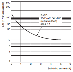
last update: April 2, 2018
OMRON E5ED / E5ED-B dimension
E5ED / E5ED-B Digital Temperature Controller (48 x 96 mm)/Dimensionslast update: December 20, 2018
(Unit: mm)
Controllers
E5ED
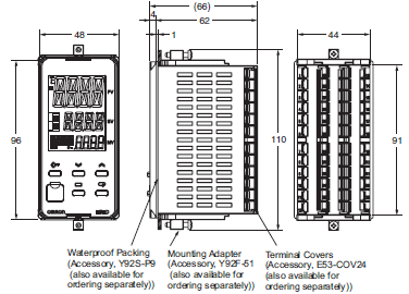
E5ED-B
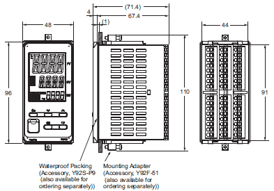
•Setup Tool ports are provided as standard feature. Use these ports to connect a computer to the Digital Temperature Controller. The E58-CIFQ2 USB-Serial Conversion Cable is required to connect to the port on the top panel. The E58-CIFQ2 USB-Serial Conversion Cable and E58-CIFQ2-E Communications Conversion Cable are required to connect to the port on the front panel. (You cannot leave either port connected constantly during operation.)
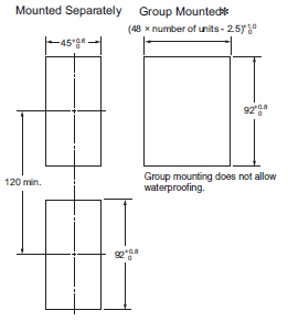
•Recommended panel thickness is 1 to 8 mm.
•Group mounting is not possible in the vertical direction. (Maintain the specified mounting space between Controllers.)
•To mount the Controller so that it is waterproof, insert the waterproof packing onto the Controller.
•When two or more Controllers are mounted, make sure that the surrounding temperature does not exceed the
allowable operating temperature specified in the specifications.
•Use a control panel thickness of 1 to 3 mm if the Y92A-49N and a USB-Serial Conver-sion Cable are used together.
* Selections for Control Outputs 1 and 2: QR or RR
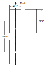
If you also specify 022 for the option selection and use group
mounting, the ambient temperature must be 45°C or less. Maintain the following spacing when more than one Digital Controller is installed at an ambient temperature of 55°C.
Accessories (Order Separately)
USB-Serial Conversion
CableE58-CIFQ2

Conversion Cable
E58-CIFQ2-E

Note:Always use this product together with the E58-CIFQ2.
Terminal Covers (Cannot be used on a Push-In Plus terminal block type)
E53-COV24 (Three Covers provided.)
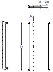
The Terminal Covers are provided with the Digital Temperature Controller.
Order the Terminal Cover separately if it becomes lost or damaged.
Waterproof Packing
Y92S-P9 (for DIN 48 × 96)

The Waterproof Packing is provided with the Digital Temperature Controller.
Order the Waterproof Packing separately if it becomes lost or damaged.
The Waterproof Packing can be used to achieve an IP66 degree of protection.
Also, keep the Port Cover on the front-panel Setup Tool port of the E5ED securely closed.
(Deterioration, shrinking, or hardening of the waterproof packing may occur depending on the operating environment. Therefore, periodic replacement is recommended to ensure the level of waterproofing specified in IP66. The time for periodic replacement depends on the operating environment. Be sure to confirm this point at your site. Consider three years as a rough standard.)
Setup Tool Port Cover for front panel
Y92S-P7
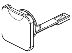
Order this Port Cover separately if the Port Cover on the front-panel Setup Tool port is lost or damaged. The Waterproof Packing must be periodically replaced because it may deteriorate, shrink, or harden depending on the operating environment.
Mounting Adapter
Y92F-51 (Two Adapters provided.)

One pair is provided with the Controller.
Order this Adapter separately if it becomes lost or damaged.
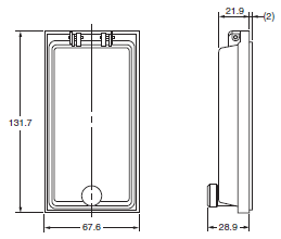
Waterproof Cover
Y92A-49N (for DIN 48 × 96)
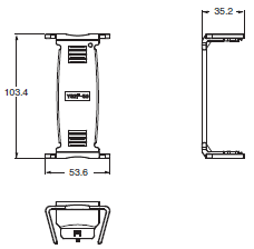
Draw-out Jig (Cannot be used on a Push-In Plus terminal block type)
Y92F-59
Use this Draw-out Jig to remove the interior body of the Digital Temperature Controller from the case to perform maintenance without removing the terminal wiring.
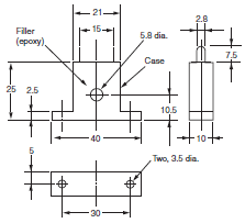
Current Transformers
E54-CT1
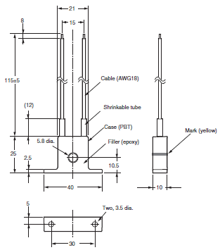
E54-CT1L
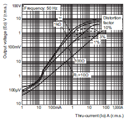
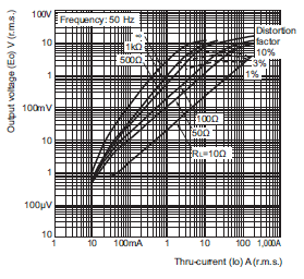
Thru-current (Io) vs. Output Voltage (Eo)
(Reference Values)
E54-CT1 or E54-CT1L
Maximum continuous heater current: 50 A (50/60 Hz)
Number of windings: 400±2
Winding resistance: 18±2 Ω
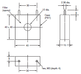
E54-CT3
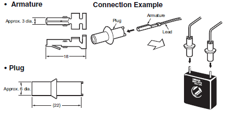
E54-CT3 Accessories
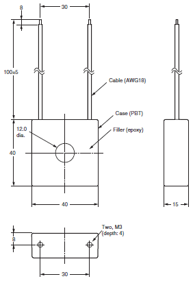
E54-CT3L
Thru-current (Io) vs. Output Voltage (Eo)
(Reference Values)
E54-CT3 or E54-CT3L
Maximum continuous heater current: 120 A (50/60 Hz)
(Maximum continuous heater current for an OMRON Digital Temperature Controller is 50 A.)
Number of windings: 400±2
Winding resistance: 8±0.8 Ω
last update: December 20, 2018
OMRON E5ED / E5ED-B catalog
E5ED / E5ED-B Digital Temperature Controller (48 x 96 mm)/Catalog- Catalog
- Manual
- CAD
English
Global Edition
| Catalog Name | Catalog Number [size] | Last Update | |
|---|---|---|---|
| | H223-E1-03 [14694KB] | Dec 20, 201820181220 | E5[]D Data Sheet |
| | H222-E1-03 [3882KB] | Jan 07, 201920190107 | E5[]D/NX-TC Catalog |
| | Y218-E1-03 [13592KB] | Oct 02, 201720171002 | Innovation in Control Panel Building |
OMRON E5ED / E5ED-B lineup
E5ED / E5ED-B Digital Temperature Controller (48 x 96 mm)/Lineuplast update: October 2, 2017
Model Number Legend
Models with Screw Terminal Blocks
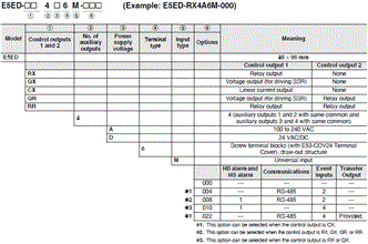
Heating and Cooling Control
Using Heating and Cooling Control
(1) Control Output Assignment
If there is no control output 2, an auxiliary output is used as the cooling control output.
If there is a control output 2, the two control outputs are used for heating and cooling.
(It does not matter which output is used for heating and which output is used for cooling.)
(2) Control
If PID control is used, you can set PID control separately for heating and cooling.
This allows you to handle control systems with different heating and cooling response characteristics.
List of Models
| Model |
|---|
| E5ED-RX4A6M-000 |
| E5ED-RX4D6M-000 |
| E5ED-RX4A6M-008 |
| E5ED-RX4D6M-008 |
| E5ED-RX4A6M-010 |
| E5ED-RX4D6M-010 |
| E5ED-QX4A6M-000 |
| E5ED-QX4D6M-000 |
| E5ED-QX4A6M-008 |
| E5ED-QX4D6M-008 |
| E5ED-QX4A6M-010 |
| E5ED-QX4D6M-010 |
| E5ED-CX4A6M-000 |
| E5ED-CX4D6M-000 |
| E5ED-CX4A6M-004 |
| E5ED-CX4D6M-004 |
| E5ED-CX4A6M-022 |
| E5ED-CX4D6M-022 |
| E5ED-RR4A6M-000 |
| E5ED-RR4A6M-008 |
| E5ED-QR4A6M-000 |
| E5ED-QR4A6M-008 |
Model Number Legend
Models with Push-In Plus Terminal Blocks
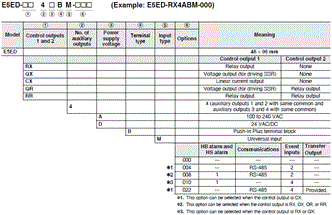
Heating and Cooling Control
Using Heating and Cooling Control
(1) Control Output Assignment
If there is no control output 2, an auxiliary output is used as the cooling control output.
If there is a control output 2, the two control outputs are used for heating and cooling. (It does not matter which output is used for heating and which output is used for cooling.)
(2) Control
If PID control is used, you can set PID control separately for heating and cooling.
This allows you to handle control systems with different heating and cooling response characteristics.
List of Models
| Model |
|---|
| E5ED-RX4ABM-000 |
| E5ED-RX4DBM-000 |
| E5ED-RX4ABM-008 |
| E5ED-RX4DBM-008 |
| E5ED-RX4ABM-010 |
| E5ED-RX4DBM-010 |
| E5ED-QX4ABM-000 |
| E5ED-QX4DBM-000 |
| E5ED-QX4ABM-008 |
| E5ED-QX4DBM-008 |
| E5ED-QX4ABM-010 |
| E5ED-QX4DBM-010 |
| E5ED-CX4ABM-000 |
| E5ED-CX4DBM-000 |
| E5ED-CX4ABM-004 |
| E5ED-CX4DBM-004 |
| E5ED-CX4ABM-022 |
| E5ED-CX4DBM-022 |
| E5ED-RR4ABM-000 |
| E5ED-RR4ABM-008 |
| E5ED-QR4ABM-000 |
| E5ED-QR4ABM-008 |
Optional Products (Order Separately)
USB-Serial Conversion Cable
| Model |
|---|
| E58-CIFQ2 |
Communication Conversion Cable
| Model |
|---|
| E58-CIFQ2-E |
Note:Always use this product together with the E58-CIFQ2.
Terminal Covers
(Cannot be used on a Push-In Plus terminal block type)
| Model |
|---|
| E53-COV24 (3pcs) |
Note:Terminal Covers are provided with the Digital Temperature Controller.
Waterproof Packing
| Model |
|---|
| Y92S-P9 |
Note:This Waterproof Packing is provided with the Digital Temperature Controller.
Waterproof Cover
| Model |
|---|
| Y92A-49N |
Front Port Cover
| Model |
|---|
| Y92S-P7 |
Note:This Front Port Cover is provided with the Digital Controller.
Mounting Adapter
| Model |
|---|
| Y92F-51 (2pcs) |
Note:This Mounting Adapter is provided with the Digital Temperature Controller.
Current Transformers (CTs)
| Hole diameter | Model |
|---|---|
| 5.8 mm | E54-CT1 |
| 5.8 mm | E54-CT1L* |
| 12.0 mm | E54-CT3 |
| 12.0 mm | E54-CT3L* |
*Lead wires are included with these CTs. If UL certification is required, use these CTs.
Draw-out Jig
(Cannot be used on a Push-In Plus terminal block type)
| Model |
|---|
| Y92F-59 |
CX-Thermo Support Software
| Model |
|---|
| EST2-2C-MV4 |
Note:CX-Thermo version 4.66 or higher is required for the E5ED.
CX-Thermo version 4.67 or higher is required for the E5ED-B.
For the system requirements for the CX-Thermo, refer to information on the EST2-2C-MV4.
last update: October 2, 2017
- NO. E5ED / E5ED-B
- TYPE:Temperature Controllers General-purpose
 Copyright Statement
 - DATE:2021-06-09
- Associated products:
E5CD / E5CD-B Digital Temperature Controller (48 x 48 mm)/Features E5GC Digital Temperature Controller (48 × 24 mm)/Features