OMRON EE-SPY31 / 41Sensors/ Photomicro Sensors/Limited-reflective
OMRON EE-SPY31 / 41 Sensors
- EE-SPY31 / 41 Light Convergent Reflective Photomicrosensor/Catalog
- EE-SPY31 / 41 Light Convergent Reflective Photomicrosensor/Dimensions
- EE-SPY31 / 41 Light Convergent Reflective Photomicrosensor/Specifications
- EE-SPY31 / 41 Light Convergent Reflective Photomicrosensor/Lineup
- Purchase the OMRON EE-SPY31 / 41 Limited-reflective
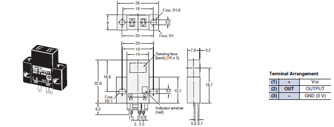
OMRON EE-SPY31 / 41 Dimensions
/Images/l_443-25-118806-198x198.jpglast update: April 19, 2017
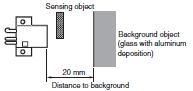
• A shiny background can be used as long as the distance between the sensor and the background is 20 mm or more.
• Detects minute objects such as a 0.05-mm-dia. pure copper wire.
• Small dispersion in sensing distance.
• Light modulation effectively reduces external light interference.
• Wide operating voltage range: 5 to 24 VDC
last update: April 19, 2017
Purchase the OMRON Limited-reflective Please fill in the following
If you have just landed here, this product OMRON EE-SPY31 / 41 Sensors,Sensors is offered online by Tianin FLD Technical Co.,Ltd. This is an online store providing Sensors at wholesale prices for consumers. You can call us or send enquiry, we would give you the prices, packing,deliverty and more detailed information on the EE-SPY31 / 41 We cooperate with DHL,TNT,FEDEX,UPS,EMS,etc.They guarantee to meet your needs in terms of time and money,even if you need your OMRON EE-SPY31 / 41Sensors tomorrow morning (aka overnight or next day air) on your desk, 2, 3 days or more.Note to international customers, YES, we ship worldwide.
E3T Ultracompact, Ultrathin Photoelectric Sensor with Built-in Amplifier/Features
ZX-T Smart Sensors High-Precision Contact Type/Features
E5CSV Temperature Controllers/Features
E5C2 Temperature Controller/Features
CPM1A-SRT21 I/O Link Unit/Features
OMRON EE-SPY31 / 41 catalog
EE-SPY31 / 41 Light Convergent Reflective Photomicrosensor/Catalog- Catalog
- Manual
- CAD
English
Global Edition
| Catalog Name | Catalog Number [size] | Last Update | |
|---|---|---|---|
| | - [520KB] | Jan 05, 201720170105 | EE-SPY31/SPY41 Data Sheet |
OMRON EE-SPY31 / 41 dimension
EE-SPY31 / 41 Light Convergent Reflective Photomicrosensor/Dimensionslast update: November 12, 2012
Tolerance class IT16 applies to dimensions in this datasheet unless otherwise specified.
Sensors
EE-SPY311
EE-SPY411
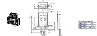
EE-SPY312
EE-SPY412
last update: November 12, 2012
OMRON EE-SPY31 / 41 specification
EE-SPY31 / 41 Light Convergent Reflective Photomicrosensor/Specificationslast update: September 23, 2012
| Models | EE-SPY311, EE-SPY411, EE-SPY312, EE-SPY412 | |
|---|---|---|
| Sensing distance | 2 to 5 mm (Reflection factor: 90%; white paper 15 × 15 mm) | |
| Minimum sensing object | Pure copper wire (0.05 mm dia.) | |
| Distance to background *1 | 20 mm max. (glass with aluminum deposition) | |
| Differential distance | 0.2 mm (with a sensing distance of 3 mm, horizontally) | |
| Light source | GaAs infrared LED with a peak wavelength of 940 nm | |
| Indicator *2 | Light indicator (red) | |
| Supply voltage | 5 to 24 VDC ±10%, ripple (p-p): 5% max. | |
| Current consumption | Average: 15 mA max., Peak: 50 mA max. | |
| Control output | NPN voltage output: Load power supply voltage: 5 to 24 VDC Load current: 80 mA max. OFF current: 0.5 mA max. 80 mA load current with a residual voltage of 1.0 V max. 10 mA load current with a residual voltage of 0.4 V max. | |
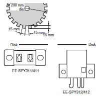
| Response frequency *3 | 100 Hz min. | |
| Ambient illumination | 3,000 lx max. with incandescent light or sunlight on the surface of the receiver | |
| Ambient temperature range | Operating: - 10 to +55 ° C Storage: - 25 to +65 ° C | |
| Ambient humidity range | Operating: 5% to 85% Storage: 5% to 95% | |
| Vibration resistance | Destruction: 10 to 50 Hz, 1.5-mm double amplitude for 2 h each in X, Y, and Z directions | |
| Shock resistance | Destruction: 500m/s2 for 3 times each in X, Y, and Z directions | |
| Degree of protection | IEC IP50 | |
| Connecting method | Special connector (soldering not possible) | |
| Weight | Approx. 2.6 g | |
| Material | Case | Polycarbonate |
| Holder | Polybutylene phthalate (PBT) | |
*1.
*2. The indicator is a GaP red LED (peak wavelength: 700 nm).
*3. The response frequency was measured by detecting the following rotating disk.
last update: September 23, 2012
OMRON EE-SPY31 / 41 lineup
EE-SPY31 / 41 Light Convergent Reflective Photomicrosensor/Lineuplast update: January 05, 2017
Sensors
| Appearance | Sensing method | Sensing distance | Output type | Output configuration | Model | |
|---|---|---|---|---|---|---|
| Horizontal type |  | Convergent reflective type | 2 to 5 mm (Infrared light) | NPN output | Dark-ON | EE-SPY311 |
| Light-ON | EE-SPY411 | |||||
| Vertical type |  | Dark-ON | EE-SPY312 | |||
| Light-ON | EE-SPY412 | |||||
Accessories (Order Separately)
| Type | Cable length | Model | |
|---|---|---|---|
| Connector | Connector | EE-1001 | |
| EE-1009 * | |||
| Connector with Cable | 1 m | EE-1006 1M | |
| EE-1010 1M * | |||
| 2 m | EE-1006 2M | ||
| EE-1010 2M * | |||
| Connector with Robot Cable | 1 m | EE-1010-R 1M * | |
| 2 m | EE-1010-R 2M * | ||
| NPN/PNP Conversion Connector | 0.46 m (total length) | EE-2002 | |
Note: Refer to Accessories for details.
* EE-1009- or EE-1010-series Connectors have a builtin locking mechanism to prevent cable disconnection when only the cable is pulled. To remove the Connector from the Sensor, grip the top and bottom of the Connector firmly and push into the Sensor once before pulling out. The locking mechanism prevents the Connector from being removed by pulling on the cable only and enables removal only when the Connector (housing) is pulled.
last update: January 05, 2017
- NO. EE-SPY31 / 41
- TYPE:Photomicro Sensors Limited-reflective
 Copyright Statement
 - DATE:2021-06-16
- Associated products:
EE-SPX301 / 401, EE-SPY30 / 40 Slot-type Reflective Photomicrosensor/Features EE-SY671 / 672 Reflective Photomicrosensor with Sensitivity Adjuster (Non-modulated)/Features