OMRON E2EMSensors/ Proximity Sensors/Cylindrical
OMRON E2EM Sensors
OMRON E2EM Dimensions
/Images/l_450-25-118697-198x198.jpglast update: April 21, 2017
• Long-distance detection at up to 30 mm enables secure mounting with reduced problems due to workpiece collisions.
• No polarity for easy wiring with DC 2-wire models.
• Cable protector provided as a standard feature.
last update: April 21, 2017
Purchase the OMRON Cylindrical Please fill in the following
If you have just landed here, this product OMRON E2EM Sensors,Sensors is offered online by Tianin FLD Technical Co.,Ltd. This is an online store providing Sensors at wholesale prices for consumers. You can call us or send enquiry, we would give you the prices, packing,deliverty and more detailed information on the E2EM We cooperate with DHL,TNT,FEDEX,UPS,EMS,etc.They guarantee to meet your needs in terms of time and money,even if you need your OMRON E2EMSensors tomorrow morning (aka overnight or next day air) on your desk, 2, 3 days or more.Note to international customers, YES, we ship worldwide.
G70D-SOC16 / FOM16 Relay Terminal/Features
CJ1W-B7A CJ-series B7A Interface Unit/Features
CRT1B-[]D02JS(-1) / []D04JS(-1) Bit Slave Units with Compact Connectors/Features
Cobra 450 SCARA Robots/Features
D6FZ-FGS Series Air Flow Sensor/Features
OMRON E2EM lineup
E2EM Long-distance Proximity Sensor/Lineuplast update: January 14, 2014
Sensors
DC 2-Wire, Pre-wired Models
| Appearance | Sensing distance | Model | ||
|---|---|---|---|---|
| NO | NC | |||
 *1 | M12 | 4 mm | E2EM-X4X1 2M *2 | E2EM-X4X2 2M |
| M18 | 8 mm | E2EM-X8X1 2M *2 | E2EM-X8X2 2M | |
| M30 | 15 mm | E2EM-X15X1 2M *2 | E2EM-X15X2 2M | |
 | M18 | 16 mm | E2EM-X16MX1 2M | E2EM-X16MX2 2M |
| M30 | 30 mm | E2EM-X30MX1 2M | E2EM-X30MX2 2M | |
*1. There are installation restrictions that apply to Shielded Sensors. Refer to Reference Influence of Surrounding Metal
in Safety Precautions on Data Sheet.
*2. Pre-wired M12 Connector Models with a cable length of 300 mm are also available. Add -M1J to the end of the model
number (example: E2EM-X4X1-M1J).
DC 3-Wire, Pre-wired Models
| Appearance | Sensing distance | Model | ||
|---|---|---|---|---|
| Output configuration: NPN NO | Output configuration: NPN NC | |||
| * | M8 | 2 mm | E2EM-X2C1 2M | E2EM-X2C2 2M |
| M12 | 4 mm | E2EM-X4C1 2M | E2EM-X4C2 2M | |
| M18 | 8 mm | E2EM-X8C1 2M | E2EM-X8C2 2M | |
| M30 | 15 mm | E2EM-X15C1 2M | E2EM-X15C2 2M | |
* There are installation restrictions that apply to Shielded Sensors. Refer to Reference Influence of Surrounding Metal in
Safety Precautions on Data Sheet.
DC 3-Wire, M12 Connector Models
| Appearance | Sensing distance | Model | ||
|---|---|---|---|---|
| Output configuration: NPN NO | Output configuration: NPN NC | |||
 * | M8 | 2 mm | E2EM-X2C1-M1 | E2EM-X2C2-M1 |
| M12 | 4 mm | E2EM-X4C1-M1 | E2EM-X4C2-M1 | |
| M18 | 8 mm | E2EM-X8C1-M1 | E2EM-X8C2-M1 | |
| M30 | 15 mm | E2EM-X15C1-M1 | E2EM-X15C2-M1 | |
* There are installation restrictions that apply to Shielded Sensors. Refer to Reference Influence of Surrounding Metal in
Safety Precautions on Data Sheet.
Accessories (Order Separately)
Sensor I/O Connectors (M12, Sockets on One Cable End)
(Models for Connectors and with Pre-wired Connectors: A Connector is not provided with the Sensor. Be sure to order a Connector separately.)
| Appearance | Cable length | Sensor I/O Connector model number | Applicable Proximity Sensor model number |
|---|---|---|---|
 | 2 m | XS2F-D421-DC0-F | E2EM-X[]C1-M1 |
| 5 m | XS2F-D421-GC0-F | ||
| 2 m | XS2F-D421-D80-F | E2EM-X[]C[]-M1 | |
| 5 m | XS2F-D421-G80-F | ||
 | 2 m | XS2F-D422-DC0-F | E2EM-X[]C1-M1 |
| 5 m | XS2F-D422-GC0-F | ||
| 2 m | XS2F-D422-D80-F | E2EM-X[]C[]-M1 | |
| 5 m | XS2F-D422-G80-F |
Note: Refer to Introduction to Sensor I/O Connectors/Sensor Controllers for details.
Use the XS2F-D42[]-[]CO-A for the E2EM-X[]X1-M1J. (Terminal 3: 0 V (+V), Terminal 4: +V (0 V))
last update: January 14, 2014
OMRON E2EM specification
E2EM Long-distance Proximity Sensor/Specificationslast update: July 13, 2017
E2EM-X[]X[] DC 2-Wire Models
| Size | M12 | M18 | M30 | |||
|---|---|---|---|---|---|---|
| Shielded | Shielded | Shielded | Unshielded | Shielded | Unshielded | |
| Model | E2EM-X4X[] | E2EM-X8X[] | E2EM-X16MX[] | E2EM-X15X[] | E2EM-X30MX[] | |
| ensing distance | 4 mm ±10% | 8 mm ±10% | 16 mm ±10% | 15 mm ±10% | 30 mm ±10% | |
| Set distance *1 | 0 to 3.2 mm | 0 to 6.4 mm | 0 to 12.8 mm | 0 to 12 mm | 0 to 24 mm | |
| Differential travel | 15% max. of sensing distance | |||||
| Detectable object | Ferrous metal (The sensing distance decreases with non-ferrous metal. Refer to Engineering Data on Data Sheet.) | |||||
| Standard sensing object | Iron, 12 × 12 × 1 mm | Iron, 18 × 18 × 1 mm | Iron, 45 × 45 × 1 mm | Iron, 30 × 30 × 1 mm | Iron, 70 × 70 × 1 mm | |
| Response frequency *2 | 1 kHz | 0.5 kHz | 0.4 kHz | 0.25 kHz | 0.1 kHz | |
| Power supply voltage (operating voltage range) | 12 to 24 VDC (10 to 30 VDC), ripple (p-p): 10% max. | |||||
| Leakage current | 0.8 mA max. | |||||
| Control output | Load current | 3 to 100 mA | ||||
| Residual voltage *3 | 5 V max. (Load current: 100 mA, Cable length: 2 m) | |||||
| Indicators | X1 Models: Operation indicator (red), Setting indicator (green) X2 Models: Operation indicator (red) | |||||
| Operation mode (with sensing object approaching) | X1 Models: NO X2 Models: NC Refer to the timing charts under I/O Circuit Diagrams on Data Sheet for details. | |||||
| Protection circuits | Surge suppressor, Load short-circuit protection | |||||
| Ambient temperature range | Operating: -25 to 70°C, Storage: -40 to 85°C (with no icing or condensation) | |||||
| Ambient humidity range | Operating/Storage: 35% to 95% (with no condensation) | |||||
| Temperature influence | ±15% max. of sensing distance at 23°C in the temperature range of -25 to 70°C | |||||
| Voltage influence | ±1% max. of sensing distance at rated voltage in the rated voltage ±15% range | |||||
| Insulation resistance | 50 MΩ min. (at 500 VDC) between current-carrying parts and case | |||||
| Dielectric strength | 1,000 VAC, 50/60 Hz for 1 minute between current-carrying parts and case | |||||
| Vibration resistance | Destruction: 10 to 55 Hz, 1.5-mm double amplitude for 2 hours each in X, Y, and Z directions | |||||
| Shock resistance | Destruction: 1,000 m/s2 10 times each in X, Y, and Z directions | |||||
| Degree of protection | IEC 60529 IP67, in-house standards: oil-resistant | |||||
| Connection method | Pre-wired Models (Standard cable length: 2 m) | |||||
| Weight (packed state) | Approx. 60 g | Approx. 130 g | Approx. 150 g | Approx. 180 g | Approx. 210 g | |
| Materials | Case | Nickel-plated brass | ||||
| Sensing surface | PBT | |||||
| Clamping nuts | Nickel-plated brass | |||||
| Toothed washer | Zinc-plated iron | |||||
| Accessories | Instruction manual | |||||
*1. Use the Sensor within the range in which the setting indicator (green LED) is ON (except X2 Models).
*2. The response frequency is an average value.
Measurement conditions are as follows: standard sensing object, a distance of twice the standard sensing object,
and a set distance of half the sensing distance.
*3. The residual voltage is 5 V. Make sure that the device connected to the Sensor can withstand the residual voltage.
(Refer to Data Sheet for details.)
E2EM-X[]C[] DC 3-Wire Models
| Size | M8 | M12 | M18 | M30 | |
|---|---|---|---|---|---|
| Shielded | Shielded | Shielded | Shielded | Shielded | |
| Model | E2EM-X2C[](-M1) | E2EM-X4C[](-M1) | E2EM-X8C[](-M1) | E2EM-X15C[](-M1) | |
| Sensing distance | 2 mm ±10% | 4 mm ±10% | 8 mm ±10% | 15 mm ±10% | |
| Set distance | 0 to 1.6 mm | 0 to 3.2 mm | 0 to 6.4 mm | 0 to 12 mm | |
| Differential travel | 10% max. of sensing distance | ||||
| Detectable object | Ferrous metal (The sensing distance decreases with non-ferrous metal. Refer to Engineering Data on Data Sheet.) | ||||
| Standard sensing object | Iron, 8 × 8 × 1 mm | Iron, 12 × 12 × 1 mm | Iron, 18 × 18 × 1 mm | Iron, 30 × 30 × 1 mm | |
| Response frequency *1 | 1.5 kHz | 0.5 kHz | 0.3 kHz | 0.1 kHz | |
| Power supply voltage (operating voltage range) *2 | 12 to 24 VDC (10 to 30 VDC), ripple (p-p): 10% max. | ||||
| Current consumption | 13 mA max. | ||||
| Control output | Load current *2 | 200 mA max. | |||
| Residual voltage | 2 V max. (Load current: 200 mA, Cable length: 2 m) | ||||
| Indicators | Operation indicator (yellow) | ||||
| Operation mode (with sensing object approaching) | C1 Models: NO C2 Models: NC Refer to the timing charts under I/O Circuit Diagrams on Data Sheet for details. | ||||
| Protection circuits | Reverse polarity protection, Load short-circuit protection, Surge suppressor | ||||
| Ambient temperature range *1 | Operating/Storage: -40 to 85°C (with no icing or condensation) | Operating: -25 to 70°C Storage: -40 to 85°C (with no icing or condensation) | |||
| Ambient humidity range | Operating/Storage: 35% to 95% (with no condensation) | ||||
| Temperature influence | ±15% max. of sensing distance at 23°C in the temperature range of -40 to 85°C ±10% max. of sensing distance at 23°C in the temperature range of -25 to 70°C | ±15% max. of sensing distance at 23°C in the temperature range of -25 to 70°C | |||
| Voltage influence | ±1% max. of sensing distance at rated voltage in the rated voltage ±15% range | ||||
| Insulation resistance | 50 MΩ min. (at 500 VDC) between current-carrying parts and case | ||||
| Dielectric strength | 1,000 VAC, 50/60 Hz for 1 minute between current-carrying parts and case | ||||
| Vibration resistance | Destruction: 10 to 55 Hz, 1.5-mm double amplitude for 2 hours each in X, Y, and Z directions | ||||
| Shock resistance | Destruction: 500 m/s2 10 times each in X, Y, and Z directions | Destruction: 1,000 m/s2 10 times each in X, Y, and Z directions | |||
| Degree of protection | Pre-wired Models: IEC 60529 IP67, in-house standards: oil-resistant Connector Models: IEC 60529 IP67 | ||||
| Connection method | Pre-wired Models (Standard cable length: 2 m) Connector Models | ||||
| Weight (packed state) | Pre-wired Models | Approx. 65 g | Approx. 75 g | Approx. 150 g | Approx. 195 g |
| Connector Models | Approx. 15 g | Approx. 25 g | Approx. 40 g | Approx. 90 g | |
| Materials | Case | Stainless steel (SUS303) | Nickel-plated brass | ||
| Sensing surface | PBT | ||||
| Clamping nuts | Nickel-plated brass | ||||
| Toothed washer | Zinc-plated iron | ||||
| Accessories | Instruction manual | ||||
*1. The response frequency is an average value.
Measurement conditions are as follows: standard sensing object, a distance of twice the standard sensing object,
and a set distance of half the sensing distance.
*2. When using an M8 Model at an ambient temperature between 70 and 85°C, supply 10 to 30 VDC to the Sensor and
make sure that the Sensor has a control output of 100 mA maximum.
last update: July 13, 2017
OMRON E2EM dimension
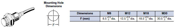
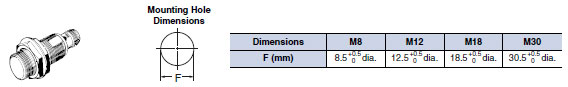
E2EM Long-distance Proximity Sensor/Dimensionslast update: October 15, 2012
Note:Tolerance class IT16 applies to dimensions in this data sheet unless otherwise specified.
Pre-wired Models (Shielded)
E2EM-X2C[]
![E2EM Dimensions 4 E2EM-X2C[]_Dim](/images/8767/E2EM_dm_225-112819.jpg)
E2EM-X4[][]
![E2EM Dimensions 5 E2EM-X4[][]_Dim](/images/8767/E2EM_dm_325-112821.jpg)
E2EM-X8[][]
![E2EM Dimensions 7 E2EM-X8[][]_Dim](/images/8767/E2EM_dm_425-112824.jpg)
E2EM-X15[][]
![E2EM Dimensions 8 E2EM-X15[][]_Dim](/images/8767/E2EM_dm_525-112826.jpg)
Pre-wired Models
(Unshielded)
E2EM-X16MX[]
![E2EM Dimensions 12 E2EM-X16MX[]_Dim](/images/8767/E2EM_dm_725-112830.jpg)
E2EM-X30MX[]
![E2EM Dimensions 14 E2EM-X30MX[]_Dim](/images/8767/E2EM_dm_825-112832.jpg)
Connector Models
(Shielded )
E2EM-X2C[]-M1
![E2EM Dimensions 17 E2EM-X2C[]-M1_Dim](/images/8767/E2EM_dm_1025-112836.jpg)
E2EM-X4C[]-M1
![E2EM Dimensions 18 E2EM-X4C[]-M1_Dim](/images/8767/E2EM_dm_1125-112838.jpg)
E2EM-X8C[]-M1
![E2EM Dimensions 19 E2EM-X8C[]-M1_Dim](/images/8767/E2EM_dm_1225-112840.jpg)
E2EM-X15C[]-M1
![E2EM Dimensions 20 E2EM-X15C[]-M1_Dim](/images/8767/E2EM_dm_1325-112842.jpg)
last update: October 15, 2012
OMRON E2EM catalog
E2EM Long-distance Proximity Sensor/Catalog- Catalog
- Manual
- CAD
English
Global Edition
| Catalog Name | Catalog Number [size] | Last Update | |
|---|---|---|---|
| | - [822KB] | Jul 13, 201720170713 | E2EM Data Sheet |
- NO. E2EM
- TYPE:Proximity Sensors Cylindrical
 Copyright Statement
 - DATE:2021-06-17
- Associated products:
E2E Standard Proximity Sensor/Features E2V-X[] All Metals and Long-distance Types/Features