OMRON NLSwitches/ Limit Switches/Touch Switches
OMRON NL Switches
OMRON NL Dimensions
/Images/l_563-25-118995-198x198.jpglast update: April 21, 2017
• Instantaneous operation upon contact with extremely limited hysteresis for high-precision position detection.
• Detects minute displacement or lightweight objects with minimal operating force.
• Built-in LED indicator ensures easy operation monitoring.
• DC models provide versatile functions in combination with the S3D2 Sensor Controller.
last update: April 21, 2017
Purchase the OMRON Touch Switches Please fill in the following
If you have just landed here, this product OMRON NL Switches,Switches is offered online by Tianin FLD Technical Co.,Ltd. This is an online store providing Switches at wholesale prices for consumers. You can call us or send enquiry, we would give you the prices, packing,deliverty and more detailed information on the NL We cooperate with DHL,TNT,FEDEX,UPS,EMS,etc.They guarantee to meet your needs in terms of time and money,even if you need your OMRON NLSwitches tomorrow morning (aka overnight or next day air) on your desk, 2, 3 days or more.Note to international customers, YES, we ship worldwide.
R88M-K, R88D-KN[]-ML2 G5-series AC Servomotors/Servo Drives with Built-in MECHATROLINK-II Communi...
E2EM Long-distance Proximity Sensor/Features
NE1A-SCPU Series Safety Network Controller/Features
S8VK-X Switch Mode Power Supply (60/120/240/480-W Models)/Features
K8AK-PW Three-phase Voltage Relay/Features
OMRON NL lineup
NL Limit Touch Switch/Lineuplast update: November 06, 2012
Built-in Antenna Model
| Model | Built-in antenna model | ||
|---|---|---|---|
| Features | Provides sufficient OT (overtravel). Antenna tip withstands bending. | Ensures high-precision positioning control. OT of 5-mm max. (overtravel) | |
| Antenna | Coil spring | Plunger | |
| Series | Power supply voltage | Model | Model |
| NL1 | 12 VDC | NL1-C | NL1-P |
| NL2 | 24 VDC | NL2-C | NL2-P |
| NL3 | 100 VAC | NL3-C 100V | NL3-P 100V |
| 200 VAC | NL3-C 200V | NL3-P 200V | |
| Antenna only | NL1-C ANTENNA ASSY (Same for NL1, NL2, and NL3) | --- | |
Note: Each model is provided with a standard 1-m cable.
Separate Antenna Model
| Model | Separate antenna model | |||
|---|---|---|---|---|
| Features | Antenna with 3-m extension cable is available for narrow spaces where conventional limit switches cannot be used. | |||
| Antenna | No antenna | Plunger with antenna | Coil spring with antenna | |
| Series | Power supply voltage | Model | Model | Model |
| NL1 | 12 VDC | NL1-S | NL1-SP | NL1-SC |
| NL2 | 24 VDC | NL2-S | NL2-SP | NL2-SC |
| Antenna only | --- | --- | NL1-SC ANTENNA (Same for NL1 and NL2) | |
Note: Each model is provided with a standard 1-m cable.
last update: November 06, 2012
OMRON NL specification
NL Limit Touch Switch/Specificationslast update: November 06, 2012
| Model | NL1 | NL2 | NL3 |
|---|---|---|---|
| Degree of protection | IP60 | ||
| Supply voltage | 12 VDC | 24 VDC | 100 VAC or 200 VAC |
| Rated frequency | --- | 50/60 Hz | |
| Sensitivity | Grounded object: Contact resistance of 3 kΩ max. Non-grounded object: Antenna-to-ground capacitance of 100 pF min. | ||
| Current consumption | 8 mA | 15 mA | --- |
| Leakage current | --- | Circuit: 2 mA; Antenna: 1 mA *1 | |
| Response time | 5 ms max. | 20 ms max. | |
| Output signal | Voltage output model: 30 mA at 12 VDC with output impedance of 4.7 kΩ | Current output model: 24 VDC (directly switching resistive load of 170 mA max.) | Thyristor output model: 100 or 200 VAC (directly switching resistive load of 30 to 300 mA) *2 |
| Insulation resistance | 0 V (blue lead wire) is connected to casing | 100 MΩ min. at 500 VDC *3 | |
| Dielectric strength | 0 V (blue lead wire) is connected to casing | 1,500 VAC at 50/60 Hz for 1 min *3 | |
| Pollution degree (operating environment) | 3 (IEC947-5-1) | ||
| Protection against electric shock | Class II | ||
| Proof tracking index (PTI) | 175 | ||
| Switch category | D (IEC335) | ||
| Vibration resistance | 10 to 55 Hz, 1.5-mm double amplitude | ||
| Shock resistance | 200 m/s2 max. | ||
| Ambient temperature | -10°C to +60°C (with no icing) | ||
| Ambient humidity | 35% to 95%RH | ||
| Weight | Approx. 370 g (NL[]-C, -P) Approx. 550 g (NL[]-S) Approx. 680 g (NL[]-SP, -SC) | ||
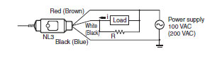
*1. The NL3 has a capacitor and resistor for the protection of the built-in SCR. Therefore, the NL3 has leakage current.
*2. The NL3 requires a current of 30 mA for circuit protection.
If the load current is less than 30 mA, connect the bleeder resistance R in parallel with the load as shown below so
that the total current of the load circuit will be 30 to 300 mA.
Obtain R from the following formula.

Make sure that the permissible power of the resistor is sufficient.
*3. Between current-carrying and non-current-carrying metal parts
last update: November 06, 2012
OMRON NL catalog
NL Limit Touch Switch/Catalog- Catalog
- CAD
English
Global Edition
| Catalog Name | Catalog Number [size] | Last Update | |
|---|---|---|---|
| | - [811KB] | Aug 29, 201220120829 | NL Data Sheet |
OMRON NL dimension
NL Limit Touch Switch/Dimensionslast update: November 06, 2012
Built-in Antenna Models
Coil Spring
NL1-C
NL2-C
NL3-C
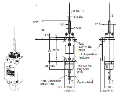
*1. The coil spring antenna is movable in any direction. Make sure that the angle of the antenna is within 30° to the FP
(free position) after the antenna comes into contact with the object.
*2. Use after removing the caution label.
Note: 1. The force that pushes the actuator must not exceed 1.96 N.
2. The antenna is replaceable. Contact your OMRON representative for details.
Plunger
NL1-P
NL2-P
NL3-P
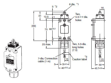
*1. The stainless-steel plunger antenna allows a maximum OT (overtravel) of 5 mm.
*2. This position is the FP (free position) of the plunger.
*3. Use after removing the caution label.
Note: Do not apply a force greater than 9.8 N to the plunger.
Separated Antenna Models
The dimensions provided for the NL1-SP, NL2-SP, NL1-SC, and NL2-SC are the external dimensions for the antennas. The casing dimensions of these models are all the same as those for the coil spring or plunger models.
No Antenna
NL1-S
NL2-S
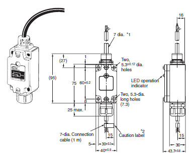
*1. A standard 3-m high-frequency coaxial cable is provided.
*2. Use after removing the caution label.
Note: 1. Make sure that the shape of the antenna is suitable to the application.
Use the plunger antenna or coil spring antenna as shown right for the NL1-S or NL2-S.
2. Do not cut or extend the connecting cable.
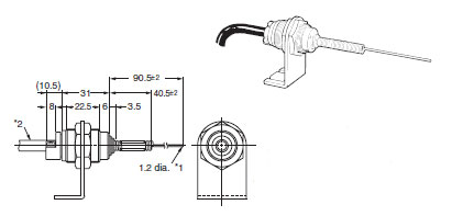
Plunger Antenna
NL1-SP
NL2-SP
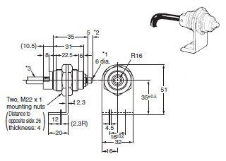
*1. The stainless-steel plunger antenna allows a maximum OT (overtravel) of 5 mm.
*2. This position is the FP (free position) of the plunger.
*3. A standard 3-m high-frequency coaxial cable is provided.
Note: 1. Do not apply a force greater than 9.8 N to the plunger.
2. Do not cut or extend the connecting cable.
Coil Spring Antenna
NL1-SC
NL2-SC
*1. The coil spring antenna is movable in any direction. Make sure that the angle of the antenna is within 30° to the FP
(free position) after the antenna comes into contact with the object.
*2. A standard 3-m high-frequency coaxial cable is provided.
Note: 1. Do not cut or extend the connecting cable.
2. The antenna is replaceable. Contact your OMRON representative for details.
Note: Unless otherwise specified, a tolerance of ±0.4 mm applies to all dimensions.
last update: November 06, 2012
- NO. NL
- TYPE:Limit Switches Touch Switches
 Copyright Statement
 - DATE:2021-06-07
- Associated products:
D5C Touch Switch/Features VB Multiple Limit Switch/Features