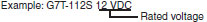
OMRON G7TRelays/ General Purpose Relays/For Control Panel
OMRON G7T Relays
OMRON G7T Dimensions
/Images/l_952-25-118878-198x198.jpglast update: December 19, 2013
• SPST-NO, SPST-NC, and SPDT contact forms available for output (SPST-NO only for input).
• Ultra-slim housing measuring 29 (W) x 10 (D) x 32 (H) mm.
• All Output Relays provide a long endurance (1,000,000 operations at 5 A), while all Input Relays provide microswitching power (100 μA at 1 V).
• Approved by UL and CSA standards.
last update: December 19, 2013
Purchase the OMRON For Control Panel Please fill in the following
If you have just landed here, this product OMRON G7T Relays,Relays is offered online by Tianin FLD Technical Co.,Ltd. This is an online store providing Relays at wholesale prices for consumers. You can call us or send enquiry, we would give you the prices, packing,deliverty and more detailed information on the G7T We cooperate with DHL,TNT,FEDEX,UPS,EMS,etc.They guarantee to meet your needs in terms of time and money,even if you need your OMRON G7TRelays tomorrow morning (aka overnight or next day air) on your desk, 2, 3 days or more.Note to international customers, YES, we ship worldwide.
E3S-DB Transparent Object Detection Photoelectric Sensor/Features
E6D-C High-resolution Encoder with Diameter of 55 mm/Features
H3DK-H Power OFF-delay Timer/Features
CS1D CS1D Overview/Features
M7E (25 mm) Digital Display (25 mm)/Features
OMRON G7T catalog
G7T I/O Relay/Catalog- Catalog
- Manual
- CAD
English
Global Edition
| Catalog Name | Catalog Number [size] | Last Update | |
|---|---|---|---|
| | - [598KB] | Jul 01, 201620160701 | G7T Data Sheet |
OMRON G7T lineup
G7T I/O Relay/Lineuplast update: October 14, 2015
When your order, specify the rated voltage.
| Classification | Model | Rated voltage | |
|---|---|---|---|
| Input (bifurcated contact) | SPST-NO | G7T-1122S (see note 2) | 12 VDC |
| 24 VDC | |||
| 100/110 VAC | |||
| 200/220 VAC | |||
| Output (single contact) | SPST-NO | G7T-1112S (see note 2) | 12 VDC |
| 24 VDC | |||
| SPST-NC | G7T-1012S | 12 VDC | |
| 24 VDC | |||
| SPDT | G7T-112S | 12 VDC | |
| 24 VDC | |||
Note: 1. When ordering, add the rated voltage to the model number. Rated voltages are given in the coil ratings table in
Specifications.
2. The G7T-1122S and G7T-1112S are approved by UL and CSA. Contact your OMRON representative for the coil
ratings of other models. The G7T-112S cannot be used in place of the G7TC. The G7T-112S can only be used
with the P7TF-05 Socket.
3. "Input" and "output" indicate the I/O relationship to a PLC. Input Relays are mainly suitable for input signals to
a PLC or other device. Output Relays are mainly suitable to switching loads that receive output signals from a
PLC or other device. The Input and Output Relays have different switching performances. Select a suitable
Relay for the application.
Accessories
Socket
| Applicable Relay | Model |
|---|---|
| All G7T I/O Relay and the G3TA models. | P7TF-05 |
P70 Indicator Module
Remove the transparent style strip of the Socket and mount this module. It will function as an operation indicator with surge suppression.
| Model | Applicable Relay coil voltage | Remarks | |
|---|---|---|---|
| For AC Relay | P70A | 100/110 VAC | Surge suppressing system with varistor |
| 200/220 VAC | |||
| For DC Relay | P70D | 12/24 VDC | Surge suppressing system with diode |
Note: 1. Order the Indicator Module that is suited to the Relay coil voltage.
2. The Indicator Module for DC Relays has a multiple power supply common to 12 and 24 VDC.
3. Input current (reference values):
100/110 VAC: 1.14 to 1.38 mA
200/220 VAC: 1.40 to 1.71 mA
12/24 VDC: 4.83 to 5.90 mA
last update: October 14, 2015
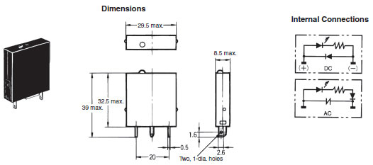
OMRON G7T dimension
G7T I/O Relay/Dimensionslast update: November 12, 2012
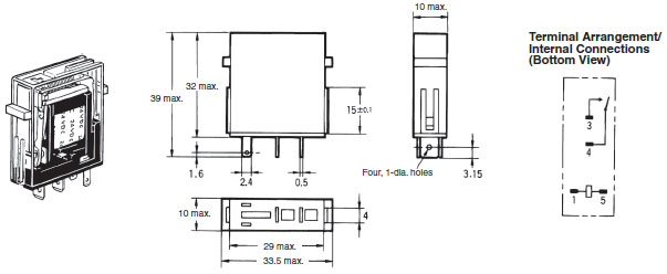
I/O Relay
SPST-NO Type
G7T-1122S (for input)
G7T-1112S (for output)
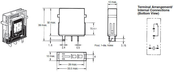
SPST-NC Type
G7T-1012S (for output)
SPDT Type
G7T-112S (for output)
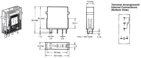
Note: This Relay cannot be used as an I/O relay terminals and must be used in combination with the exclusive P7TF-05
Socket.
Accessories
Socket
P7TF-05
Note: If the I/O SSR or Indicator Module is used, be aware that the polarity of terminal 1 is positive.
* We recommend that you insert washers when mounting with M3 screws. A washers are not required when mounting
with M4 screws.
Indicator Module (with Surge Suppressing Function)
P70
last update: November 12, 2012
OMRON G7T specification
G7T I/O Relay/Specificationslast update: July 01, 2016
Ratings
Coil Ratings (Common to Both Input and Output)
| Rated voltage (V) | Rated current | Coil resistance | Must operate voltage | Must release voltage | Max. voltage | Power consumption | ||
|---|---|---|---|---|---|---|---|---|
| 50 Hz | 60 Hz | |||||||
| AC | 100/110 | 8.2/9 mA | 7/7.7 mA | 8,700 Ω | 80% max. of rated value | 30% min. of rated value | 110% of rated value | 0.7 VA |
| 200/220 | 4.1/4.5 mA | 3.5/3.85 mA | 33,300 Ω | |||||
| DC | 12 | 42 mA | 290 Ω | 80% max. of rated value | 10% min. of rated value | 110% of rated value | 0.5 W | |
| 24 | 21 mA | 1,150 Ω | ||||||
| 100/110 | 5 mA | 20,000 Ω | 80% max. of rated value | 10% min. of rated value | 110% of rated value | 0.5 W | ||
Note: 1. The rated current and coil resistance values are measured at a coil temperature of 23°C. Tolerances of AC rated
current are +15%, –20% and tolerances of coil resistance are ±15%.
2. Four rated voltages or currents are available to single AC models used with the P7TF-05 Socket. Only three
rated voltages or currents are available, however, when the Relay is used in place of the G7TC.
3. The operating characteristics values are for a coil temperature of 23°C.
4. The maximum voltage is one that is applicable to the Relay coil instantaneously at 23°C and not continuously.
Contact Ratings
| Classification | For input | For output | ||
|---|---|---|---|---|
| Resistive load (cosΦ = 1) | Inductive load (L/R = 7 ms) | Resistive load (cosΦ = 1) | Inductive load (cosΦ = 0.4, L/R = 7 ms) | |
| Contact mechanism | Crossbar bifurcated | Single | ||
| Contact material | AgAu-clad Ag | AgSnIn | ||
| Rated load | 1 A at 24 VDC | 0.5 A at 24 VDC | 5 A at 24 VDC 2 A at 220 VAC | 2 A at 24 VDC 1 A at 220 VAC |
| Rated carry current | 1 A | 5 A | ||
| Max. switching voltage | 250 VAC, 125 VDC | |||
| Max. switching current | 1 A | 5 A | ||
| Failure rate (reference value) | 100 μA at 1 VDC | 10 mA at 5 VDC | ||
Characteristics
| Contact resistance (see note 2) | 50 mΩ max. |
|---|---|
| Operate time (see note 3) | 15 ms max. |
| Release time (see note 3) | 15 ms max. |
| Max. operating frequency | Mechanical: 18,000 operations/hour Electrical: 1,800 operations/hour (under rated load) |
| Insulation resistance (see note 4) | 100 MΩ (at 500 VDC) |
| Dielectric strength | Between coil and contacts: 2,000 VAC, 50/60 Hz for 1 minute Between contacts of same polarity: 1,000 VAC, 50/60 Hz for 1 minute |
| Vibration resistance | Malfunction: 10 to 55 to 10 Hz, 0.5 mm single amplitude (1.0 mm double amplitude) |
| Shock resistance | Malfunction: 200 m/s2 |
| Mechanical endurance | 50,000,000 operations |
| Electrical endurance (see note 5) | Input: 10,000,000 operations (10 mA) or 50,000 operations (1 A) with resistive load 2,500,000 operations (10 mA) or 20,000 operations (1 A) with inductive load Output: 1,000,000 operations with rated load |
| Error rate (level P) (Reference value) (see note 6) | Input: 100 μA at 1 VDC Output: 10 mA at 5 VDC |
| Ambient temperature | Operating: -40°C to 70°C (with no icing or condensation) |
| Ambient humidity | Operating: 5% to 85% (with no icing or condensation) |
| Weight | Approx. 17 g |
Note: 1. The above values are all initial values.
2. The contact resistance was measured with 1 A at 5 VDC using the voltage drop method.
3. The operate and the release times were measured with the rated voltage imposed with any contact bounce
ignored at an ambient temperature of 23°C.
4. The insulation resistance was measured with a 500-VDC megger applied to the same places as those used
for checking the dielectric strength.
5. The electrical endurance was measured at an ambient temperature of 23°C.
6. This value was measured at a switching frequency of 120 operations per minute.
Socket Ratings
Features
- Easily mounts or dismounts the G7T I/O Relay.
- Also mounts the Indicator Module (with surge suppressing function).
- Only 19 mm in width.
- Terminals corresponding to the NO and NC contacts of a Relay are arranged on top of the Socket to enhance maintainability.
- Also permits mounting of the G3TA Solid-state I/O Relay.
Specifications
| Model | P7TF-05 |
|---|---|
| Contact resistance | 10 mΩ max. |
| Dielectric strength | 2,000 VAC for 1 minute |
| Insulation resistance | 1,000 MΩ min. (at 500 VDC) |
| Vibration resistance | 10 to 55 to 10 Hz, 0.5 mm single amplitude (1.0 mm double amplitude) |
| Shock resistance | 1,000 m/s2 |
| Ambient temperature | Operating:-40°C to 70°C (with no icing or condensation) |
| Ambient Humidity | Operating: 5% to 85%RH |
| Weight | Approx. 28 g |
* Measurement condition: 1 A at 5 VDC.
last update: July 01, 2016
- NO. G7T
- TYPE:General Purpose Relays For Control Panel
 Copyright Statement
 - DATE:2021-06-10
- Associated products:
G2RV Slim Relay/Features MK-S General-purpose Relays/Features