OMRON G3J-T-CRelays/ Solid-state Relays/For Three-phase Motors
OMRON G3J-T-C Relays
- G3J-T-C Solid State Contactor for 3-phase Motors with Built-in Soft Start/Stop and Monitor Output/Lineup
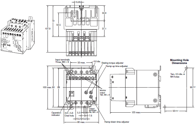
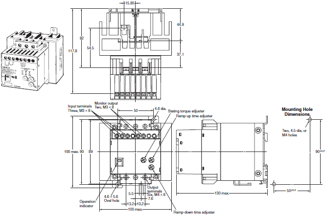
- G3J-T-C Solid State Contactor for 3-phase Motors with Built-in Soft Start/Stop and Monitor Output/Dimensions
- G3J-T-C Solid State Contactor for 3-phase Motors with Built-in Soft Start/Stop and Monitor Output/Catalog
- G3J-T-C Solid State Contactor for 3-phase Motors with Built-in Soft Start/Stop and Monitor Output/Specifications
- Purchase the OMRON G3J-T-C For Three-phase Motors
OMRON G3J-T-C Dimensions
/Images/l_979-25-118860-198x198.jpglast update: January 7, 2019
• Limiting the starting current saves energy.
• Certified for UL, CSA, and CCC.
• Mounts with screws or to DIN Track.
• Compact design with heat sinks (3.7-kW models: 100 × 100 × 130 mm (W × H × D)).
• Built-in snubber circuit and thyristor.
• Built-in operation indicator.
last update: January 7, 2019
Purchase the OMRON For Three-phase Motors Please fill in the following
If you have just landed here, this product OMRON G3J-T-C Relays,Relays is offered online by Tianin FLD Technical Co.,Ltd. This is an online store providing Relays at wholesale prices for consumers. You can call us or send enquiry, we would give you the prices, packing,deliverty and more detailed information on the G3J-T-C We cooperate with DHL,TNT,FEDEX,UPS,EMS,etc.They guarantee to meet your needs in terms of time and money,even if you need your OMRON G3J-T-CRelays tomorrow morning (aka overnight or next day air) on your desk, 2, 3 days or more.Note to international customers, YES, we ship worldwide.
NB-S Series Programmable Terminal/Features
A30NS / A30NW Selector Switches/Features
NX-TC NX-series Temperature Control Unit/Features
CRT1B-[]D02S(-1) Bit Slave Units with e-CON Connectors/Features
DRT2-[]D04CL(-1) / []D08C(-1) / []D08CL(-1) / []D16C(-1) / []D16CL(-1) Environment-resistive Term...
OMRON G3J-T-C lineup
G3J-T-C Solid State Contactor for 3-phase Motors with Built-in Soft Start/Stop and Monitor Output/Lineuplast update: November 06, 2012
| Number of elements | Isolation method | Rated power supply voltage | Input method | Applicable monitor capacity (AC3) | Monitor output | Model | |
|---|---|---|---|---|---|---|---|
| 3 | Phototriac coupler | 100 to 240 VAC | No-voltage input (open and short- circuited input) | 3.7 kW (17.4 A) | 200 to 220 VAC | AC switching output | G3J-T217BL-C AC100-240 |
| 2.2 kW (11.1 A) | G3J-T211BL-C AC100-240 | ||||||
| 0.75 kW (4.8 A) | G3J-T205BL-C AC100-240 | ||||||
| 12 to 24 VDC | 3.7 kW (17.4 A) | DC switching output | G3J-T217BL-C DC12-24 | ||||
| 2.2 kW (11.1 A) | G3J-T211BL-C DC12-24 | ||||||
| 0.75 kW (4.8 A) | G3J-T205BL-C DC12-24 | ||||||
last update: November 06, 2012
OMRON G3J-T-C dimension
G3J-T-C Solid State Contactor for 3-phase Motors with Built-in Soft Start/Stop and Monitor Output/Dimensionslast update: November 06, 2012
G3J-T205BL-C
G3J-T211BL-C

G3J-T217BL-C

last update: November 06, 2012
OMRON G3J-T-C catalog
G3J-T-C Solid State Contactor for 3-phase Motors with Built-in Soft Start/Stop and Monitor Output/Catalog- Catalog
- Manual
- CAD
English
Global Edition
| Catalog Name | Catalog Number [size] | Last Update | |
|---|---|---|---|
| | - [911KB] | Jan 07, 201920190107 | G3J-T-C Data Sheet |
| | - [300KB] | Aug 24, 201220120824 | Safety Precautions for the G3J-T-C, G3J-T, G3J-S, and G3J |
OMRON G3J-T-C specification
G3J-T-C Solid State Contactor for 3-phase Motors with Built-in Soft Start/Stop and Monitor Output/Specificationslast update: January 7, 2019
Certified Standards
UL 508, CSA 22.2 No. 14, CCC GB/T 14048.6 No. 2016010304855599
Ratings (at an Ambient Temperature of 25°C)
Power Supply
| Operating input power supply specifications | AC Model | DC Model |
|---|---|---|
| Rated power supply voltage | 100 to 240 VAC | 12 to 24 VDC |
| Operating voltage range | 85 to 264 VAC | 10.2 to 26.4 VDC |
| Current consumption | 40 mA max. (at 100 to 240 VAC) | 70 mA max. (at 12 to 24 VDC) |
Operating (Input) Circuit
AC Model
| Input method | No-voltage input | Short-circuiting/opening terminals 3 and 1 or terminals 3 and 2 SSR input short-circuited: Maximum impedance of 1 kΩ , Maximum residual voltage of 1 V SSR input open: Minimum impedance of 100 kΩ Relay input: For minute signals |
|---|
DC Model
| Input current | 10 mA max. (at 12 to 24 VDC) | |
|---|---|---|
| Input method | No-voltage input | Short-circuiting/opening terminals 3 and 1 or terminals 3 and 2 SSR input turned ON: Maximum residual voltage of 2 V between short-circuited terminals SSR input turned OFF: Maximum leakage current of 0.15 mA Relay input: For minute signals |
Main Circuit (for Both AC and DC Models)
| Model | G3J-T217BL-C | G3J-T211BL-C | G3J-T205BL-C | |
|---|---|---|---|---|
| Rated load voltage | 200 to 240 VAC | |||
| Rated voltage range | 180 to 264 VAC | |||
| Rated carry current *1 | 17.4 A (at 40 °C) | 11.1 A (at 40 °C) | 4.8 A (at 40 °C) | |
| Minimum load current | 0.5 A | |||
| Inrush current resistance (peak value) | 500 A (60 Hz, 1 cycle) | 350 A (60 Hz, 1 cycle) | 150 A (60 Hz, 1 cycle) | |
| Overload resistance | Refer to Engineering Data on Catalog. | |||
| Closed current (effective value) | AC3 | 174 A | 111 A | 48 A |
| AC4 | 208.8 A | 133.2 A | 57.6 A | |
| Breaking current (effective value) | AC3 | 139.2 A | 88.8 A | 38.4 A |
| AC4 | 174 A | 111 A | 48 A | |
| Applicable load | 3-phase inductive motor *2 (AC3, AC4, AC53-a) | 200 to 220 VAC 3.7 kW (17.4 A) | 200 to 220 VAC 2.2 kW (11.1 A) | 200 to 220 VAC 0.75 kW (4.8 A) |
| Resistive load (AC1) *3 | 200 to 240 VAC, 17.4 A | 200 to 240 VAC, 11.1 A | 200 to 240 VAC, 4.8 A | |
*1. The rated carry load depends on the ambient temperature. For details, refer to the Load Current vs. Ambient
Temperature graph in Engineering Data.
*2. Satisfies switching test conditions of AC3, AC4, and AC53-a. (Refer to Engineering Data on Data Sheet for the test
conditions.)
*3. Single-phase loads cannot be used.
Monitor Output
| Operating input power supply specifications | AC model | DC model |
|---|---|---|
| Rated power supply voltage | 100 to 240 VAC | 12 to 24 VDC |
| Operating voltage range | 85 to 264 VAC | 10.2 to 26.4 VDC |
| Rated carry current | 50 mA | 0.2 A |
| Minimum load current | 3 mA | 3 mA |
Characteristics (for Both AC and DC Models)
| Model | G3J-T217BL-C | G3J-T211BL-C | G3J-T205BL-C |
|---|---|---|---|
| Ramp-up time | Set within a range of approx. 1 to 25 s. | ||
| Ramp-down time | Set within a range of approx. 1 to 25 s. | ||
| Starting torque *1 | Set within a range of 200% to 450% In. | ||
| Monitor output operate time *2 | After control signal input: AC model: 300 ms max. (TYP 50 ms), DC model: 50 ms max. | ||
| Monitor output release time *2 | After ramp-down time completion (after main circuit current turns OFF): 60 ms max. | ||
| Output ON voltage drop (main circuit) | 1.6 V (RMS) max. | ||
| Output ON voltage drop (monitor output) | AC model: 3.5 VAC max., DC model: 2.0 VDC max. | ||
| Leakage current (main circuit) | 10 mA max. (at 200 VAC) | ||
| Leakage current (monitor output) | AC model: 1.5 mA max. (at 200 VAC), DC model: 0.15 mA max. (at 24 VDC) | ||
| Insulation resistance | 100 MΩ min. (at 500 VDC) | ||
| Dielectric strength | 2,500 VAC, 60 Hz for 1 min | ||
| Vibration resistance | 10 to 55 to 10 Hz, 0.75-mm single amplitude (1.5-mm double amplitude) | ||
| Shock resistance | 294 m/s2 | ||
| Storage temperature | - 30 to 70 °C (with no icing or condensation) | ||
| Ambient operating temperature | - 20 to 60 °C (with no icing or condensation) | ||
| Ambient operating humidity | 45 to 85 % | ||
| Weight | Approx. 890 g | Approx. 760 g | Approx. 760 g |
*1. Provided that the starting torque is 600% In when the motor is started at full voltage.
*2. The monitor output will be ON while load current is flowing to the main circuit.
last update: January 7, 2019
- NO. G3J-T-C
- TYPE:Solid-state Relays For Three-phase Motors
 Copyright Statement
 - DATE:2021-06-11
- Associated products:
G3NB Solid State Relays/Features G3J-T Soft-start/stop Solid State Contactors/Features