
OMRON FQM1 SeriesMotion / Drives/ Motion Controllers/ Copyright Statement
OMRON FQM1 Series Motion / Drives
OMRON FQM1 Series Dimensions
/Images/l_1558-25-136185-198x198.jpglast update: December 13, 2013
Advanced Power in Three Applications: Motion Control, Measurement Control, and High-speed Response Control

Compatible with NEW Servo and CJ-series Analog Units (Unit version Ver.3.3 or higher)
The FQM1 has become compatible with NEW AC Servo Motors/Drivers OMNUC G-series and SMARTSTEP 2-series, in addition to the conventional OMNUC W-series. Also, new analog units are included in CJ-series Units to be used for FQM1 expansion.
Compatible with NEW AC Servo Motors/Drivers OMNUC G-series (OMNUC G-series R88D-GT/R88M-G)

The FQM1 corresponds with the absolute value encoder interface of the special and high performance OMNUC G-series.
Compatible with Various CJ-series Analog Units

In addition to conventional high-speed type Analog Input Units (CJ1W-ADG41), Analog Input Units (8/4 points), Analog output Units (8/4/2 points), and Analog I/O Units (AD 4/DA 2 points) can be used.
For the Non-stop Control
Ideal for Applications Performing Processing
without Stopping Machinery Operation
To improve machinery performance, it important to increase productivity by eliminating waste.
Here, the FQM1 really performs to enable processing must be achieved without stopping machinery operation.

Connecting the FQM1 with SYSMAC SPU Units enables simplification of the changes in various control and/or operation conditions as well as high speed collection of large capacity data.
Using SYSMAC SPU Units makes time reduction for tooling change for each operation possible. Replacing memory cards also allows for easy change of operations and/or conditions. During an inspection process, not only conditional changes but also inspection results can be saved securely.

- Up to 65 (including the one basic collection pattern and data collection patterns from 1 to 64) data patterns can be collected in the data collection mode.
Various data collection is possible if combining events. - The setting information of SYSMAC SPU Units can be exported as an Excel file. The file can be used as a sheet to define and manage information on a device.
● The recipe function is used to write numeric values including operation parameters and/or character string data at one
time to the CM (Controller Module) memory area. The recipe write function makes tooling change of the device easy.
(Note: The recipe function can be used only in the "data collection mode".)
* Create numeric values and character string data to be written to the CM memory area in recipe data (CSV file) and
stored beforehand in a SYSMAC SPU Unit memory card.
● No ladder program is required to develop recipe data.
● The recipe function can save the CM memory because recipe data is saved in the memory card of a SYSMAC SPU Unit,
which eliminates the need to save it in the CM data memory.
● Recipe data can be written upon request from the CM or via external devices including a PC.
● Numeric values and character string data can be changed even when a SYSMAC SPU Unit is in operation.
A Variety of Applications Accomplished with Motion, Measurement, and High-speed Response
High-level Wide-ranging Motion Achieved from F (Flexibility) and Q (Quickness).
From High-speed PTP Control to Synchronous, Torque, and Tension Control
Pulse/analog I/O feedback gives the FQM1 power in high-speed I/O applications.

Wide-ranging FQM1 Applications
In addition to motion control, the FQM1 handles the following control areas through its ability to perform high-speed I/O processing through feedback from analog or pulse input data.
Actual applications have already been implemented.

last update: December 13, 2013
Purchase the OMRON  Copyright Statement Please fill in the following
If you have just landed here, this product OMRON FQM1 Series Motion / Drives,Motion / Drives is offered online by Tianin FLD Technical Co.,Ltd. This is an online store providing Motion / Drives at wholesale prices for consumers. You can call us or send enquiry, we would give you the prices, packing,deliverty and more detailed information on the FQM1 Series We cooperate with DHL,TNT,FEDEX,UPS,EMS,etc.They guarantee to meet your needs in terms of time and money,even if you need your OMRON FQM1 SeriesMotion / Drives tomorrow morning (aka overnight or next day air) on your desk, 2, 3 days or more.Note to international customers, YES, we ship worldwide.
ZJ-FW Fan Ionizer (Area fan type)/Features
E2C / E2C-H Separate Amplifier Proximity Sensor with Adjustment Potentiometer/Features
DST1 Series Safety I/O Terminals/Features
H3YN Solid-state Timer/Features
XW2D Slim Connector-Terminal Block Conversion Units/Features
OMRON FQM1 Series lineup
FQM1 Series Flexible Motion Controllers/Lineuplast update: December 13, 2013
International Standards
- The standards indicated in the "Standards" column are those current for UL, CSA, cULus, NK, and Lloyd standards and EC Directives as of the end of February 2008. The standards are abbreviated as follows: U: UL, U1: UL (Class I Division 2 Products for Hazardous Locations), C: CSA, US: cULus, UC1: cULus (Class I Division 2 Products for Hazardous Locations), CU: cUL, N: NK, L: Lloyd, and CE: EC Directives.
- Ask your OMRON representatives for the conditions under which the standards were met.
Basic Sets
| Name | Specifications | Model | Standards |
|---|---|---|---|
| FQM1 Pulse Set | A basic set for pulse outputs and 2 axes (3) CJ1W-PA202 + (1) FQM1-CM002 + (2) FQM1-MMP22 + (9) FQM1-TER01 | FQM1S-MC233 *1 | CE, UL approval pending *2 |
| FQM1 Analog Set | A basic set for analog outputs and 2 axes (3) CJ1W-PA205R + (1) FQM1-CM002 + (2) FQM1-MMA22 + (9) FQM1-TER01 | FQM1S-MC224 *1 | CE, UL approval pending *2 |
*1. The I/O Control Module (FQM1-IC101) is not included.
*2. UL-approved products are scheduled for shipment in March 2006.
Basic Modules
| Name | Specifications | Current consumption (A) | Model | Standards | |
|---|---|---|---|---|---|
| 5 V | 24 V | ||||
| Coordi- nator Module | Program capacity: 10 Ksteps, DM Area capacity: 32 Kwords, Built-in I/O (16 inputs and 8 outputs), I/O Area for CJ-series Basic I/O Unit: 320 bits, Serial PLC Link Area: 1,440 bits, DeviceNet Area: 9,600 bits, Built-in peripheral port, RS-232C port, and RS-422 port | 0.37 | - | FQM1-CM002 *1 | CE, UL approval pending *2 |
| Motion Control Modules | Program capacity: 10 Ksteps, DM Area capacity: 32 Kwords, Built-in I/O: 12 inputs and 8 outputs), two pulse inputs, two pulse outputs | 0.824 | - | FQM1-MMP22 | CE, UL approval pending *2 |
| Program capacity: 10 Ksteps, DM Area capacity: 32 Kwords, Built-in I/O (12 inputs and 8 outputs), 2 pulse inputs, 1 analog input, 2 analog outputs | 0.772 | 0.095 | FQM1-MMA22 | CE, UL approval pending *2 | |
| I/O Control Module | Used when CJ-series Units are connected to the FQM1. A CJ-series Expansion Rack can be connected at the same time. | 0.02 | - | FQM1-IC101 *1 | UL approval pending *4, CE |
| Power Supply Unit | 100 to 240 VAC, output capacity: 2.8 A at 5 VDC, 0.4 A at 24 VDC, total power consumption: 14 W | CJ1W-PA202 | UC1, CE, N, L | ||
| 100 to 240 VAC (with RUN output), output capacity: 5 A at 5 VDC, 0.8 A at 24 VDC, total power consumption: 25 W | CJ1W-PA205R | ||||
| 100 to 240 VAC, replacement time notification function, no RUN output, Output capacity: 5 A at 5 VDC, 0.8 A at 24 VDC, total power consumption: 25 W | CJ1W-PA205C | ||||
*1. A FQM1-TER01 End Module is included.
*2. UL-approved products are scheduled for shipment in March 2006.
Servo Relay Unit and Cables
Servo Relay Unit
| Name | Compatible Units | Compatible Drivers | Number of axes | Model | Standards |
|---|---|---|---|---|---|
| Servo Relay Unit | FQM1 | OMNUC G-series/SMARTSTEP 2 | For two axes | XW2B-80J7-12A | - |
| FQM1/CS1W-HCP | OMNUC W-series/ SMARTSTEP Junior/A-series | For two axes | XW2B-80J7-1A |
Connecting Cable on Position Control Unit for Servo Relay Unit
| Name | Compatible Drivers | Specifications | Cable length | Model | Standards | |
|---|---|---|---|---|---|---|
| Connecting Cable on Position Control Unit | OMNUC G/W-series | R88D-GT/WT | General-purpose I/O (26-pin connector) | 0.5 m | XW2Z-050J-A28 | - |
| 1 m | XW2Z-100J-A28 | |||||
| 2 m | XW2Z-200J-A28 | |||||
| Special I/O (40-pin connector) | 0.5 m | XW2Z-050J-A31 | ||||
| 1 m | XW2Z-100J-A31 | |||||
| 2 m | XW2Z-200J-A31 | |||||
| OMNUC G/W-series, SMARTSTEP 2, SMARTSTEP Junior/A-series | R88D-GT/WT, R7D-BP/ZP/AP | General-purpose I/O (26-pin connector) | 0.5 m | XW2Z-050J-A28 | ||
| 1 m | XW2Z-100J-A28 | |||||
| 2 m | XW2Z-200J-A28 | |||||
| Special I/O (40-pin connector) | 0.5 m | XW2Z-050J-A30 | ||||
| 1 m | XW2Z-100J-A30 | |||||
| 2 m | XW2Z-200J-A30 | |||||
Connecting Cable on Servo Driver for Servo Relay Unit
| Name | Compatible Units | Compatible Drivers | Cable length | Model | Standards | |
|---|---|---|---|---|---|---|
| Connecting Cable on Servo Driver | Motion Control Module FQM1-MMA22 | OMNUC G-series | For R88D-GT | 1 m | XW2Z-100J-B27 | - |
| 2 m | XW2Z-200J-B27 | |||||
| OMNUC W-series | For R88D-WT | 1 m | XW2Z-100J-B13 | |||
| 2 m | XW2Z-200J-B13 | |||||
| 1 m | XW2Z-100J-B21 | |||||
| 2 m | XW2Z-200J-B21 | |||||
| 1 m | XW2Z-100J-B22 | |||||
| 2 m | XW2Z-200J-B22 | |||||
| Motion Control Module FQM1-MMP22 | SMARTSTEP 2 | For R7D-BP | 1 m | XW2Z-100J-B30 | ||
| 2 m | XW2Z-200J-B30 | |||||
| OMNUC G-series | For R88D-GT | 1 m | XW2Z-100J-B26 | |||
| 2 m | XW2Z-200J-B26 | |||||
| SMARTSTEP Junior | For R7D-ZP | 1 m | XW2Z-100J-B20 | |||
| 2 m | XW2Z-200J-B20 | |||||
| SMARTSTEP A-series | For R7D-AP | 1 m | XW2Z-100J-B10 | |||
| 2 m | XW2Z-200J-B10 | |||||
| OMNUC W-series | For R88D-WT | 1 m | XW2Z-100J-B9 | |||
| 2 m | XW2Z-200J-B9 | |||||
| 1 m | XW2Z-100J-B23 | |||||
| 2 m | XW2Z-200J-B23 | |||||
RS-422A Communications Cable between Servo Relay Units
| Name | Specifications | Cable length | Model | Standards |
|---|---|---|---|---|
| RS-422A Communications Cable between Servo Relay Units | - | 1 m | XW2Z-100J-C1 | - |
| 2 m | XW2Z-200J-C1 |
Connecting Cable with NS-series PTs
| Name | Specifications | Model | Standards | |
|---|---|---|---|---|
| Connection Format | Cable length | |||
| Connecting Cable with NS-series PTs | Connecting Cable between NS-series PT and RS-232C port on Coordinator Module | 2 m | XW2Z-200T | - |
| 5 m | XW2Z-500T | |||
| Connecting Cable between NS-series PT and peripheral port on Coordinator Module | 2 m | XW2Z-200T-2 | ||
| 5 m | XW2Z-500T-2 | |||
Others
| Name | Specifications | Model | Standards |
|---|---|---|---|
| End Module | Connected to the right end of the FQM1 Rack. Provided with the FQM1 Sets and with the FQM1-CM002. | FQM1-TER01 | UC1, CE |
| DIN Track | Track length: 0.5 m, Height: 7.3 mm | PFP-50N | - |
| Track length: 1 m, Height: 7.3 mm | PFP-100N | - | |
| Track length: 1 m, Height: 16 mm | PFP-100N2 | - | |
| End Plate | Placed on both ends of the Controller on the DIN Track to hold the Controller in place. Two End Places are provided with the FQM1 Sets and with the FQM1-CM002. | PFP-M | - |
| RS-422A Adapter | Converts RS-232C to RS-422A/485. | CJ1W-CIF11 | UC, CE, N |
Support Software
| Name | Specifications | Model | Standards | |||
|---|---|---|---|---|---|---|
| Number of licenses | Media | |||||
| CX-One FA Integrated Tool Package Ver.3.[] | The CX-One is a package that integrates the Support Software for OMRON PLCs and components. CX-One runs on the following OS. | 1 license *1 | CD | CXONE-AL01C-V3 | - | |
| DVD *2 | CXONE-AL01D-V3 | |||||
| CX-Programmer can still be ordered individually in the following model numbers. | ||||||
| CX- Programmer Ver.8.[] | PLC programming software OS: Windows 2000 (Service Pack 3a or higher), XP, or Vista | 1 license | CD | WS02-CXPC1-V8 | - | |
| 3 licenses | CD | WS02-CXPC1-V8L03 | - | |||
| 10 licenses | CD | WS02-CXPC1-V8L10 | - | |||
*1. Site licenses are available for the CX-One (3, 10, 30, or 50 licenses).
*2. When purchasing the DVD format, verify the computer model and DVD drive specifications before purchasing.
Compatible CJ-series Units
| Name | Specifications | Current consumption (A) | Model | Stand- ards | |||
|---|---|---|---|---|---|---|---|
| 5 V | 24 V | ||||||
| CJ-series End Cover | Mounted on the right end when CJ-series Units are used for expansion. | - | CJ1W-TER01 | UC1, CE, N, L | |||
| Input Units | DC Input Units | Terminal block, 12 to 24 VDC, 10 mA, 8 inputs | 0.09 | - | CJ1W-ID201 | UC, CE, N, L | |
| Terminal block, 24 VDC, 7 mA, 16 inputs | 0.08 | - | CJ1W-ID211 | UC1, CE, N, L | |||
| Fujitsu connector, 24 VDC, 4.1 mA, 32 inputs | 0.09 | - | CJ1W-ID231 *1 | ||||
| MIL connector, 24 VDC, 4.1 mA, 32 inputs | 0.09 | - | CJ1W-ID232 *1 | ||||
| Fujitsu connector, 24 VDC, 4.1 mA, 64 inputs | 0.09 | - | CJ1W-ID261 *1 | ||||
| MIL connector, 24 VDC, 4.1 mA, 64 inputs | 0.09 | - | CJ1W-ID262 *1 | ||||
| AC Input Units | Terminal block, 100 to 120 VAC, 7 mA (100 V, 50 Hz), 16 inputs | 0.09 | - | CJ1W-IA111 | |||
| Terminal block, 200 to 240 VAC, 10 mA (200 V, 50 Hz), 8 inputs | 0.08 | - | CJ1W-IA201 | ||||
| Output Units | Relay Contact Output Units | Terminal block, 250 VAC/24 VDC max., 2 A, 8 outputs, independent contacts | 0.09 | 0.048 (0.006 × number of points ON) | CJ1W-OC201 | UC1, CE, N, L | |
| Terminal block, 250 VAC/24 VDC max., 2 A, 16 outputs, independent contacts | 0.11 | 0.06 (0.006 × number of points ON) | CJ1W-OC211 | ||||
| Transistor Output Units | Terminal block, 12 to 24 VDC, 2 A, 8 sinking outputs | 0.09 | - | CJ1W-OD201 | |||
| Terminal block, 24 VDC, 2 A, 8 sourcing outputs, load short-circuit protection, wiring disconnect detection, and alarm function | 0.11 | - | CJ1W-OD202 | ||||
| Terminal block, 12 to 24 VDC, 0.5 A, 8 sinking outputs | 0.1 | - | CJ1W-OD203 | ||||
| Terminal block, 24 VDC, 0.5 A, 8 sourcing outputs, load short-circuit protection, and alarm function | 0.1 | - | CJ1W-OD204 | ||||
| Terminal block, 12 to 24 VDC, 0.5 A, 16 sinking outputs | 0.1 | - | CJ1W-OD211 | ||||
| Terminal block, 24 VDC, 0.5 A, 16 sourcing outputs, load short-circuit protection, and alarm function | 0.1 | - | CJ1W-OD212 | ||||
| Fujitsu connector, 12 to 24 VDC, 0.5 A, 32 sinking outputs | 0.14 | - | CJ1W-OD231 *1 | ||||
| MIL connector, 12 to 24 VDC, 0.5 A, 32 sourcing outputs, load short-circuit protection, and alarm function | 0.15 | - | CJ1W-OD232 *1 | ||||
| MIL connector, 12 to 24 VDC, 0.5 A, 32 sinking outputs | 0.14 | - | CJ1W-OD233 *1 | ||||
| Fujitsu connector, 12 to 24 VDC, 0.3 A, 64 sinking outputs | 0.17 | - | CJ1W-OD261 *1 | ||||
| MIL connector, 12 to 24 VDC, 0.3 A, 64 sourcing outputs | 0.17 | - | CJ1W-OD262 *1 | ||||
| MIL connector, 12 to 24 VDC, 0.3 A, 64 sinking outputs | 0.17 | - | CJ1W-OD263 *1 | ||||
| Triac Output Unit | Terminal block, 250 VAC, 0.6 A, 8 outputs | 0.22 | - | CJ1W-OA201 | |||
| I/O Units | DC Input/ Transistor Output Units | 24 VDC, 7 mA, 16 inputs | Fujitsu connector | 0.13 | - | CJ1W-MD231 *2 | UC1, N, CE |
| 12 to 12 VDC, 0.5 A, 16 sinking outputs | |||||||
| 24 VDC, 7 mA, 16 inputs | MIL connector | 0.13 | - | CJ1W-MD232 *2 | UC1, N, L, CE | ||
| 24 VDC, 0.5 A, 16 sourcing outputs, load short-circuit protection, and alarm function | |||||||
| 24 VDC, 4.1 mA, 16 inputs | MIL connector | 0.13 | - | CJ1W-MD233 *2 | UC1, CE, N | ||
| 12 to 24 VDC, 0.5 A, 16 sinking outputs | |||||||
| 24 VDC, 4.1 mA, 32 inputs | Fujitsu connector | 0.14 | - | CJ1W-MD261 *1 | |||
| 12 to 24 VDC, 0.3 A, 32 sinking outputs | |||||||
| 24 VDC, 4.1 mA, 32 inputs | MIL connector | 0.14 | - | CJ1W-MD263 *1 | |||
| 12 to 24 VDC, 0.3 A, 32 sinking outputs | |||||||
| TTL I/O Unit | 5 VDC, 3.5 mA, 32 inputs | MIL connector | 0.19 | - | CJ1W-MD563 *1 | ||
| 5 VDC, 3.5 mA, 32 inputs | |||||||
| B7A Interface Unit | 64 inputs | 0.07 | - | CJ1W-B7A14 | UC1, CE | ||
| 64 outputs | 0.07 | - | CJ1W-B7A04 | ||||
| 32 inputs/32 outputs | 0.07 | - | CJ1W-B7A22 | ||||
| CJ- series Special I/O Units | CompoBus/S Master Units | Communications functions: Remote I/O communications Maximum number of I/O points: 256 (128 inputs/128 outputs) or 128 (64 inputs/64 outputs) | 0.15 | - | CJ1W-SRM21 | UC1, CE, N, L | |
| ID Sensor Unit | Data transfer speed: 160 bytes/scan (between CPU Unit and ID Sensor Unit) | 0.26 | 0.12 | CJ1W-V600C11 | UC, CE | ||
| Position Control Unit | Pulse train open collector/ Line driver output type | 1 axis | 0.25 | - | CJ1W-NC113/133 | UC1, CE | |
| 2 axes | - | CJ1W-NC213/233 | |||||
| 4 axes | 0.36 | - | CJ1W-NC413/433 | ||||
| Analog Input Unit | Number of inputs: 8 Signal range: 1 or 5 V; 0 to 5 V, 0 to 10 V, ±10 V, 4 to 20 mA Resolution: 1/8000 (available to set to 1/4000) *1 Conversion speed: 250 μs/point max. (available to set to 1 ms/point) *1 Accuracy (ambient temperature: 25°C): Voltage: ±0.2% of F.S. Current: ±0.4% of F.S. *2 | 0.42 | - | CJ1W-AD081-V1 | UC1, N, L, CE | ||
| Number of inputs: 4 Signal range: 1 or 5 V; 0 to 5 V, 0 to 10 V, ±10 V, 4 to 20 mA Resolution: 1/8000 (available to set to 1/4000) *1 Conversion speed: 250 μs/point max. (available to set to 1 ms/point) *1 Accuracy (ambient temperature: 25°C): Voltage: ±0.2% of F.S. Current: ±0.4% of F.S. *2 | 0.42 | - | CJ1W-AD041-V1 | ||||
| Analog Output Units | Number of outputs: 8 Signal range: 1 or 5 V; 0 to 5 V, 0 to 10 V, -10 to 10 V Resolution: 1/4000 (available to set to 1/8000) Conversion speed: 1 ms/point (available to set to 250 μs/point max.) Accuracy (ambient temperature: 25°C): ±0.3% of F.S. External connection: Removable terminal block External power supply: 24 VDC, 140 mA max. | 0.14 | 0.14 *3 | CJ1W-DA08V | UC1, N, L, CE | ||
| Number of outputs: 8 Signal range: 4 to 20 mA Resolution: 1/4000 (available to set to 1/8000) Conversion speed: 1 ms/point (available to set to 250 μs/point max.) Accuracy (ambient temperature: 25°C): ±0.3% of F.S. External connection: Removable terminal block External power supply: 24 VDC +10%,-15%, 170 mA max. | 0.14 | 0.17 *3 | CJ1W-DA08C | UC1, N, CE | |||
| Number of outputs: 4 Signal range: 1 or 5 V; 0 to 5 V, 0 to 10 V, -10 to 10 V, 4 to 20 mA Resolution: 1/4000 Conversion speed: 1 ms max./point Accuracy (ambient temperature: 25°C): Voltage output: ±0.3% of F.S. Current output: ±0.5% of F.S. External connection: Removable terminal block External power supply: 24 VDC +10%,-15%, 200 mA max. | 0.12 | 0.2 *3 | CJ1W-DA041 | UC1, N, L, CE | |||
| Number of outputs: 2 Signal range: 1 or 5 V; 0 to 5 V, 0 to 10 V, -10 to 10 V, 4 to 20 mA Resolution: 1/4000 Conversion speed: 1 ms max./point Accuracy (ambient temperature: 25°C): Voltage output: ±0.3% of F.S. Current output: ±0.5% of F.S. External connection: Removable terminal block External power supply: 24 VDC +10%,-15%, 140 mA max. | 0.12 | 0.14 *3 | CJ1W-DA021 | ||||
| Analog I/O Units | Number of inputs: 4 Signal range: 1 or 5 V; 0 to 5 V, 0 to 10 V, -10 to 10 V, 4 to 20 mA Resolution: 1/4000 (available to set to 1/8000) Conversion speed: 1 ms/point (available to set to 500 μs/point max.) Accuracy (ambient temperature: 25°C): Voltage: ±0.2% of F.S. Current: ±0.2% of F.S. | 0.58 | - | CJ1W-MAD42 | UC1, N, L, CE | ||
| Number of outputs: 2 Signal range: 1 or 5 V; 0 to 5 V, 0 to 10 V, -10 to 10 V, 4 to 20 mA Resolution: 1/4000 (available to set to 1/8000) Conversion speed: 1 ms/point (available to set to 500 μs/point max.) Accuracy (ambient temperature: 25°C): Voltage: ±0.3% of F.S. Current: ±0.3% of F.S. | |||||||
| CJ- series CPU Bus Units | Analog Input Unit (High- speed type) | Number of inputs: 4 Signal range (Resolution): ±10 V (Resolution 1/60000) 0 to 5 V, 0 to 10 V (Resolution 1/30000) 1 to 5 V, 4 to 20 mA (Resolution 1/24000) Conversion speed: 80 μs/2 points, 160 μs/4 points Accuracy (ambient temperature: 25°C): ±0.05% of F.S. | 0.65 | - | CJ1W-ADG41 | UC1, CE *4 | |
| DeviceNet Unit | Slave functions only, 32,000 points max. Communications type: Remote I/O communications slave (with fixed or user- set allocation) | 0.29 | - | CJ1W-DRM21 | UC1, CE, N, L | ||
| Position Control Unit with MECHA- TROLINK-II communica- tions | Issues the control commands using the MECHATROLINK-II synchronous communications 16 axes max. Direct operation with ladder program Control mode: Position control/Speed control/Torque control | 0.36 | - | CJ1W-NCF71 | UC1, CE | ||
| High-speed Data Collection Unit | PC card slot: CF card Type I/II × 1 slot Mount OMRON memory card HMC-EF[][][] to use Ethernet (LAN) port: 1 port (10/100BASE-TX) Automatically collects the specified data through the CJ bus at intervals of a few ms, or write the event | 0.56 | - | CJ1W-SPU01-V2 | UC1, CE | ||
| CJ-series I/O Interface Unit | One unit required on the CJ-series Expansion Rack to connect CJ-series Expansion Rack. | 0.13 | - | CJ1W-II101 | UC1, CE, N, L | ||
| CJ-series I/O Connecting Cables | Connects I/O Control Module on FQM1 Rack to I/O Interface Unit on CJ- series Expansion Rack | Cable length: 0.3 m | - | CS1W-CN313 | N, L, CE | ||
| Cable length: 0.7 m | CS1W-CN713 | ||||||
| Cable length: 2 m | CS1W-CN223 | ||||||
| Cable length: 3 m | CS1W-CN323 | ||||||
| Cable length: 5 m | CS1W-CN523 | ||||||
| Cable length: 10 m | CS1W-CN133 | ||||||
| Cable length: 12 m | CS1W-CN133-B2 | ||||||
| CJ-series Power Supply Units | 100 to 240 VAC, output capacity: 2.8 A at 5 VDC, 0.4 A at 24 VDC Total power consumption: 14 W | - | CJ1W-PA202 | UC1, N, L, CE | |||
| 100 to 240 VAC (with RUN output), output capacity: 5 A at 5 VDC, 0.8 A at 24 VDC Total power consumption: 25 W | CJ1W-PA205R | ||||||
| 100 to 240 VAC, replacement time notification function, no RUN output, output capacity: 5 A at 5 VDC, 0.8 A at 24 VDC Total power consumption: 25 W | CJ1W-PA205C | ||||||
| 24 VDC, output capacity: 5 A at 5 VDC, 0.8 A at 24 VDC Total power consumption: 25 W | CJ1W-PD025 | ||||||
| 24 VDC, output capacity: 2 A at 5 VDC, 0.4 A at 24 VDC Total power consumption: 19.6 W | CJ1W-PD022 | UC1, CE | |||||
*1. Connectors are not included with the Unit.
Either separately purchase an applicable 40-pole connector, or use an OMRON Connector Terminal Block Conversion
Unit (XW2[] series) or I/O Relay Terminal (G7[] series).
*2. Connectors are not included with the Unit.
Either separately purchase an applicable 20- or 24-pole connector, or use an OMRON Connector Terminal Block
Conversion Unit (XW2[] series) or I/O Relay Terminal (G7[] series).
*3. Externally supplied power, not internally consumed current.
*4. Approved products are scheduled for shipment in August 2007.
last update: December 13, 2013
OMRON FQM1 Series specification
FQM1 Series Flexible Motion Controllers/Specificationslast update: December 13, 2013
General Specifications
| Item | Specifications |
|---|---|
| Insulation resistance | 20 MΩ min. between AC external terminals and GR terminal at 500 VDC, *1.) |
| Dielectric strength | 2,300 VAC, 50/60 Hz between AC external terminals and GR terminal for 1 min, leakage current: 10 mA max. *1 *3 |
| 720 VAC, 50/60 Hz between DC external terminals and GR terminal for 1 min, leakage current: 10 mA max. *1 | |
| Noise immunity | Conforms to IEC61000-4-4, 2 kV (power line) |
| Vibration resistance | Conforms to JIS C0040 Amplitude: 0.075 mm (10 to 57 Hz), Acceleration: 9.8 m/s2 (57 to 150 Hz) for 80 min in X, Y, and Z directions (10 sweeps of 8 min = 80 min total) |
| Shock resistance | Conforms to JIS C0041 147 m/s2 3 times each in X, Y, and Z directions |
| Ambient operating temperature | 0 to 55 °C |
| Ambient operating humidity | 10% to 90% (with no condensation) |
| Atmosphere | No corrosive gases |
| Ambient storage temperature | - 20 to 75 °C |
| Ground | Less than 100 Ω |
| Structure | For installation in a control panel |
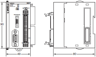
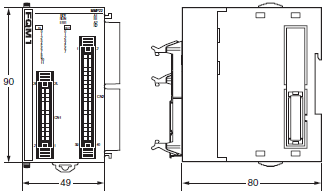
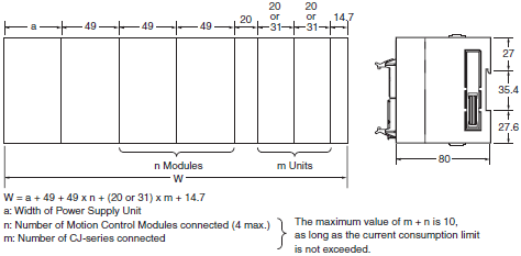
| Dimensions (mm) | 49 × 90 × 80 mm (W × H × D) excluding cable |
| Weight | 5 kg max. per Module |
| Safety standards | EC, C-Tick, UL approval pending *4 |
*1. Disconnect the LG terminal on the Power Supply Unit from the GR terminal before performing insulation resistance or
dielectric testing.
Internal components may be destroyed if testing is performed with the LR and GR terminals connected.
*2. Values for AC power are at room temperature and a cold start. Values for DC power are for a cold start. A thermistor
is used in the inrush current control circuit of the AC power supply to control current at low temperatures. The inrush
current may exceed the value given above (by up to twice the given value) when starting at high temperatures or if a
hot start is performed immediately after the current is turned OFF for a short period of time because the thermistor
element will not be sufficiently cooled. When selecting a fuse or breaker for the external circuit, consider the fusing/
detection characteristics and provide a sufficient margin in performance. A capacitor-charged delay circuit is used for
the inrush current control circuit in the DC power supply. If hot starts are performed after turning OFF the power supply
for only short periods of time, the inrush current may exceed the value given above (by up to twice the given value)
because the capacitor will not be discharged.
*3. Do not apply voltages exceeding 600 V when performing dielectric testing for the analog I/O terminals. Internal
elements may deteriorate.
*4. UL-approved products are scheduled for shipment in March 2006.
Performance
| Item | Specifications | ||||
|---|---|---|---|---|---|
| Coordinator Module | Motion Control Module | ||||
| Control method | Stored program method | Stored program method | |||
| I/O control method | Cyclic scan method | Cyclic scan method | |||
| Programming language | Ladder diagram method | Ladder diagram method | |||
| Instruction length | 1 to 7 steps/instruction | 1 to 7 steps/instruction | |||
| Number of instructions | Approx. 300 | Approx. 300 | |||
| Executing speed | Basic instructions | 0.1 μs min. | 0.1 μs min. | ||
| Special instructions | 0.3 μs min. | 0.3 μs min. | |||
| Common processing time (overhead) | Synchronous mode: 390 μs (when 1 Motion Control Module is connected) Asynchronous mode: 180 μs | FQM1- MMP22 | Synchronous mode: 250 μs Asynchronous mode: 190 μs | ||
| FQM1- MMA22 | Synchronous mode: 340 μs Asynchronous mode: 280 μs Analog outputs disabled and immediate analog inputs: 190 μs Analog input END: 230 μs | ||||
| Program capacity | Ladder | 10 Ksteps | 10 Ksteps | ||
| Comment storage | Yes | Yes | |||
| Number of tasks | Cyclic tasks: 1, Interrupt tasks: 50 | Cyclic tasks: 1, Interrupt tasks: 50 | |||
| Subroutines | 256 | 256 | |||
| JMP instruction | 256 | 256 | |||
| Number of basic I/O points | 24 | 20 per Module | |||
| CIO Area | Built-in Input Bits | 16 bits (1 word): CIO 2960.00 to CIO 2960.15 | 12 bits (1 word): CIO 2960.00 to CIO 2960.11 | ||
| Built-in Output Bits | 8 bits (1 word): CIO 2961.00 to CIO 2961.07 | 8 bits (1 word): CIO 2961.00 to CIO 2961.07 | |||
| I/O bits | 320 bits (20 words): CIO 0000 to CIO 0019 | None | |||
| CPU Bus Unit Area | 6,400 bits (400 words): CIO 1500 to CIO 1899 | None | |||
| Special I/O Unit Area | 13,760 bits (860 words): CIO 2100 to CIO 2959 | None | |||
| Cyclic Refresh Bit Area | 640 bits (40 words): CIO 4000 to CIO 4039 Refresh with Motion Module # 1: CIO 4000 to CIO 4009 Refresh with Motion Module # 1: CIO 4010 to CIO 4019 Refresh with Motion Module # 1: CIO 4020 to CIO 4029 Refresh with Motion Module # 1: CIO 4030 to CIO 4039 | 160 bits (10 words): CIO 4000 to CIO 4009 Input refresh from Coordinator Module to Motion Control Module: CIO 4000 to CIO 4004 Output refresh from Motion Control Module to Coordinator Module: CIO 4005 to CIO 4009 | |||
| Sync Data Link Bit Area | 320 bits (20 words): CIO 1200 to CIO 1219 Transmission refresh from Coordinator Module: CIO 1200 to CIO 1203 Transmission refresh from Motion Module # 1: CIO 1204 to CIO 1207 Transmission refresh from Motion Module # 2: CIO 1208 to CIO 1211 Transmission refresh from Motion Module # 3: CIO 1212 to CIO 1215 Transmission refresh from Motion Module # 4: CIO 1216 to CIO 1219 | 320 bits (20 words): CIO 1200 to CIO 1219 Transmission refresh from Coordinator Module: CIO 1200 to CIO 1203 Transmission refresh from Motion Module # 1: CIO 1204 to CIO 1207 Transmission refresh from Motion Module # 2: CIO 1208 to CIO 1211 Transmission refresh from Motion Module # 3: CIO 1212 to CIO 1215 Transmission refresh from Motion Module # 4: CIO 1216 to CIO 1219 | |||
| Serial PLC Link Bit Area (complete link method) | 1,440 bits (90 words) CIO 3100 to CIO 3189 CIO 3100 to CIO 3189: CJ1M to FQM1 CIO 3100 to CIO 3189: FQM1 to CJ1M and sources other than FQM1 (10 words each according to unit number) | None | |||
| Serial PLC Link Bit Area (master link method) | 320 bits (20 words): CIO 3100 to CIO 3119 CIO 3100 to CIO 3109: CJ1M to FQM1 CIO 3110 to CIO 3119: FQM1 to CJ1M Connectable to the host PLC (CJ1M) as a Serial PLC Link slave. | None | |||
| DeviceNet Link Bit Area | 9,600 bits (600 words): CIO 3200 to CIO 3799 | None | |||
| Internal Auxiliary Area | CIO Area | 49,792 bits: CIO 0020 to CIO 1199, CIO 1220 to CIO 1499, CIO 1900 to CIO 2099, CIO 2962 to CIO 3099, CIO 3190 to CIO 3199, CIO 3800 to CIO 3999, CIO 4040 to CIO 4999, CIO 6000 to CIO 6143 | 81,792 bits: CIO 0000 to CIO 1199, CIO 1220 to CIO 2959, CIO 2962 to CIO 3999, CIO 4010 to CIO 4999, CIO 6000 to CIO 6143 | ||
| Work Area | 4,096 bits: W000 to W255 | 4,096 bits: W000 to W255 | |||
| Auxiliary Area | READ/WRITE | Read-only: 7,168 bits (A000 to A447) Read/Write: 8,192 bits (A448 to A959) | Read-only: 7,168 bits (A000 to A447) Read/Write: 8,192 bits (A448 to A959) | ||
| Error log | 100 words: A100 to A199 (20 records) | 100 words: A100 to A199 (20 records) | |||
| TR Area | 16 bits: TR0 to TR15 | 16 bits: TR0 to TR15 | |||
| Timer Area | 256 timers: T0000 to T0255 (1-ms timers, 10-ms timers, 100-ms timers) | 256 timers: T0000 to T0255 (1-ms timers, 10-ms timers, 100-ms timers) | |||
| Counter Area | 256 counters: C0000 to C0255 (decrementing counters, reversible counters) Note: Not retained on power interruption. | 256 counters: C0000 to C0255 (decrementing counters, reversible counters) Note: Not retained on power interruption. | |||
| DM Area | Read/Write (not retained) | 20,000 words: D00000 to D19999 (Not retained on power interruption.) | 30,000 words: D00000 to D29999 (Not retained on power interruption.) *1 | ||
| Read/Write (retained) | 12,768 words: D20000 to D32767 (Saved in flash memory. Not saved when written by ladder program, however, saved in flash memory if written by Programming Device such as the CX-Programmer.) | 2,768 words: D30000 to D32767 (backed up by super capacitor) | |||
| System Setup | System Setup Area (shared by Coordinator Module, Motion Control Modules, and peripheral services), Peripheral Service Settings | System Setup Area (shared by Coordinator Module and Motion Control Modules), Motion Parameter Settings | |||
| Function block address allocation area | CIO Area | 16,000 bits (1,000 words): CIO 5000 to CIO 5999 | 16,000 bits (1,000 words): CIO 5000 to CIO 5999 | ||
| Timer Area | 100 bits: T0206 to T0255 | 100 bits: T0206 to T0255 | |||
| Counter Area | 100 bits: C0206 to C0255 | 100 bits: C0206 to C0255 | |||
| Index Registers | IR0 to IR15 (IR0 and IR1 used with the JSB instruction) Note: IR16 to IR 63 for FB/ST (used by the system) | IR0 to IR15 (IR0 and IR1 used with the JSB instruction) Note: IR16 to IR 63 for FB/ST (used by the system) | |||
| Data Registers | DR0 to DR15 Note: IR16 to IR 63 for FB/ST (used by the system) | DR0 to DR15 Note: IR16 to IR 63 for FB/ST (used by the system) | |||
| Interrupts | Input interrupts | None | 4 inputs (with countdown mode) | ||
| Timer interrupts | 1 (scheduled or one-shot interrupts) | 1 (scheduled or one-shot interrupts) | |||
| Power OFF backup function (momentary power interruptions) | Super capacitor | Super capacitor | |||
| Memory backup | Super capacitor backup | Error log | Error log, a portion of DM (for momentary interruptions) | ||
| Flash memory | User programs, System Setup, part of DM | User programs, System Setup | |||
| Trace Memory | 4,000 words | 4,000 words | |||
| Peripheral services | Peripheral port (CX-Programmer connection only), RS-232C port (Host Link, no-protocol, NT Link, Serial PLC Link (slave)), RS-422A (servo driver connection) services | Event requests from the Coordinator Module | |||
| Self-diagnosis | CPU error (WDT), memory error | CPU error (WDT), memory error | |||
| Program check functions | Checked using Programming Device | Checked using Programming Device | |||
| Super capacitor life | Approx. 100 hours (ambient temperature: 25 °C, *2.) | Approx. 100 hours (ambient temperature: 25 °C, *2.) | |||
| Clock | None | None | |||
| Power interruption detection time | AC: 10 to 25 ms (not fixed) | - | |||
| Power interruption detection delay | 0 to 10 ms | - | |||
| RUN output | Yes (When using CJ1W-PA205R) | - | |||
| Individual functions | Serial commu- nications | Peripheral port (toolbus, Host Link) Coordinator Module built-in RS-232C port (Host Link, no-protocol, NT Link, Serial PC Link (slave)) Coordinator Module built-in RS-422A port (servo driver interface, serial gateway, noprotocol) | High- speed counters | Single phase, up-down counting, pulse plus direction input (50 kHz/1 MHz), differential phase inputs (50/ 500 kHz, with phase difference multiplier of 4: 2 MHz) | |
| High- speed pulse outputs | CW/CCW (1 MHz: line-driver) one-shot pulse output | ||||
| Analog inputs | Conversion speed: 40 μs/point Resolution: -10 to 10 V: 16,000 0 to 10 V: 8,000 0 to 5 V: 4,000 1 to 5 V: 4,000 4 to 20 mA: 4,000 | ||||
| Analog outputs | Conversion speed: 40 μs/point Resolution: -10 to 10 V: 10,000 0 to 10 V, 0 to 5 V, or 1 to 5 V: 4,000 | ||||
*1. Can also be retained in flash memory. A bit can be manipulated to automatically restore the data according to a
parameter setting in the System Setup when the power supply is turned ON.
*2. Depends on the ambient temperature and number of years in use.
Coordinator Module
Built-in General-purpose I/O
| Item | Specifications | |
|---|---|---|
| Input specifications | Inputs | 16 |
| Input voltage | 20.4 to 26.4 V | |
| Input voltage | Normal inputs (16): ON response: 100 μs, OFF response: 1 ms max. 8 inputs/common | |
| Output specifications | Outputs | 8 |
| Output form | NPN transistors | |
| Switching capacity | 4.5 to 30 VDC, 0.3 A per transistor | |
| ON response time | 0.1 ms max. | |
| OFF response time | 1 ms max. | |
Motion Control Module
Built-in General-purpose I/O
| Item | Specifications | ||
|---|---|---|---|
| Input specifications | Inputs | 12 | |
| Input voltage | 20.4 to 26.4 V | ||
| Input voltage | Interrupt inputs (4) | ON response: 30 μs max. OFF response: 0.2 ms max. | |
| Normal inputs (8) | ON response: 100 μs max. OFF response: 1 ms max. | ||
| Output specifications | Outputs | 8 | |
| Output form | NPN transistors | ||
| Switching capacity | 4.5 to 30 VDC, 0.3 A per transistor | ||
| Output response | ON response: 0.1 ms max. OFF response: 1 ms max. | ||
Motion Control Module
Motion Control Module with Pulse I/O (FQM1-MMP22)
| Item | Description | |
|---|---|---|
| I/O | Pulse I/O | Pulse inputs: 2 (for servo with absolute encoder) Pulse outputs: 2 One-shot pulse outputs: 2 |
| General-purpose I/O | General-purpose inputs: 12 General-purpose outputs: 8 | |
| Functions | Pulse outputs | The following operations are possible. • Speed control (fixed speed, acceleration, and deceleration) • Position control (fixed-speed positioning, trapezoidal positioning, deceleration positioning) • Speed control based on present position (pulse output target value comparison or range comparison) • Electronic cam operation (positioning according to position of real or virtual axis) • One-shot pulse outputs (turning ON an output for a specified time, minimum unit: 0.01 ms) • Timing using pulse counter (minimum unit: 0.001 ms) |
| Pulse inputs | • High-speed counters: Single phase, up-down counting, pulse plus direction input (50 kHz/1 MHz), differential phase inputs (50/500 kHz, with multiplier of 4: 2 MHz) • Starting/stopping high-speed counters with Counter Start Bit • Measuring change in high-speed counter present value • Measuring high-speed counter frequency | |
Motion Control Module with Analog I/O (FQM1-MMA22)
| Item | Description | |
|---|---|---|
| General-purpose I/O | Pulse inputs | Pulse inputs: 2 (for servo with absolute encoder) |
| Analog I/O | • Analog inputs: 1 (-10 to 10 V, 0 to 10 V, 0 to 5 V, 1 to 5 V, and 4 to 20 mA), Conversion speed: 40 μs/point • Analog outputs: 2 (-10 to 10 V, 0 to 10 V, 0 to 5 V, and 1 to 5 V), Conversion speed: 40 μs/point | |
| General-purpose I/O | General-purpose inputs: 12 General-purpose outputs: 8 | |
| Functions | Analog outputs | • Slope function • Output hold function • Offset gain adjustment |
| Analog inputs | • Offset gain adjustment • High-speed analog sampling | |
List of Support Functions Depending on the Unit Version
O: Supported, −: Not supported
| Module type | Coordinator Module | Motion Control Module | |||
|---|---|---|---|---|---|
| Model | FQM1-CM002 | FQM1-MMP22/MMA22 | |||
| Unit version | Ver. 3.2 or higher | Ver. 3.3 or higher | Ver. 3.2 or higher | Ver. 3.3 or higher | |
| Descriptions | |||||
| Compatible with OMUNC G-series Servo ABS | - | - | - | O | |
| Addition of compatible CJ-series Units • Analog input • Analog I/O • Analog output | - | O | - | - | |
| Addition of compatible CJ-series Units CJ1W-NC[][]3/CJ1W-V600C1[] | O | O | - | - | |
| Addition of expanded cyclic refresh area | O | O | - | - | |
| Expansion with AXIS instruction function | O | O | O | O | |
| Expansion with PULS instruction (electronic cam mode) function | - | - | O *1 | O *1 | |
| Compatible with 1 Hz pulse output | - | - | O *1 | O *1 | |
| Interrupt task startup when a counter is reset | - | - | O | O | |
| Compatible with high-speed analog sampling multiple settings | - | - | O *2 | O *2 | |
*1. Only available with FQM1-MMP22.
*2. Only available with FQM1-MMA22.
Types of the Unit Version
| Name | Model | Unit Ver. |
|---|---|---|
| Coordinator Module | FQM1-CM002 | Unit Ver. 3.3 Unit Ver. 3.2 Unit Ver. 3.1 Unit Ver. 3.0 |
| Motion Control Module | FQM1-MMP22 FQM1-MMA22 | Unit Ver. 3.3 Unit Ver. 3.2 Unit Ver. 3.1 Unit Ver. 3.0 |
Relations between the Unit Version and Support Software
| Functions to be used * 1 | Support Software required CX-Programmer | |||||
|---|---|---|---|---|---|---|
| Ver. 3.3 | Ver. 4.0 | Ver. 5.0/ Ver. 6.0 | Ver. 7.0 or higher | |||
| Unit Ver. 3.3 | Functions enhanced in Unit Ver. 3.3 | to be used | × | × | × | O *2 |
| not to be used | O | O | O | O | ||
| Unit Ver. 3.2 | Functions enhanced in Unit Ver. 3.2 | to be used | × | × | O | O |
| not to be used | O | O | O | O | ||
*1. When the functions enhanced in version upgrade are not used, the CX-Programmer version does not need to be
upgraded.
*2. To perform the OMUNC G-series Servo ABS settings from the system setup menu, use the CX-Programmer Ver. 7.1 or
higher.
last update: December 13, 2013
OMRON FQM1 Series dimension
FQM1 Series Flexible Motion Controllers/Dimensionslast update: December 13, 2013
Coordinator Module
FQM1-CM002
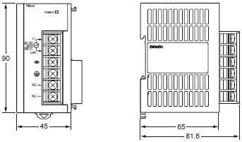
Power Supply Units
CJ1W-PA202
Motion Control Modules
FQM1-MMP22/MMA22
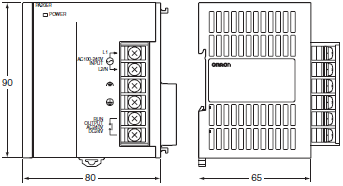
Power Supply Units
CJ1W-PA205R
End Module
FQM1-TER01

I/O Control Module
FQM1-IC101
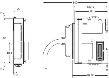
Assembled Dimensions
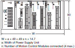
FQM1 Expanded Using CJ-series Units
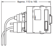
Height with Cables Connected
Height with Peripheral Port and RS-232C Port Connected
Servo Relay Unit
XW2B-80J7-1A
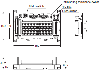
XW2B-80J7-12A
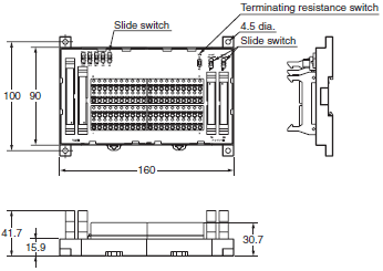
last update: December 13, 2013
OMRON FQM1 Series catalog
FQM1 Series Flexible Motion Controllers/Catalog- Catalog
- Manual
- CAD
English
Global Edition
| Catalog Name | Catalog Number [size] | Last Update | |
|---|---|---|---|
| | O901-E1-03 [9499KB] | Oct 30, 201420141030 | FQM1 Series Catalog |
- NO. FQM1 Series
- TYPE:Motion Controllers
 Copyright Statement
  Copyright Statement
 - DATE:2021-06-09
- Associated products:
CS1W-NC[][]3 SYSMAC CS-series Position Control Units/Features CS1W-MC Motion control units/Features