
OMRON EJ1Control Components/ Temperature Controllers/Module Type
OMRON EJ1 Control Components
OMRON EJ1 Dimensions
/Images/l_1757-25-118814-198x198.jpglast update: December 19, 2013
• The compact modular structure enables construction of temperature systems optimally suited to the application.
• Connection can be made to a Programmable Controller without any programming required, reducing the number of steps required in ladder programming design.
• One fully universal-input Unit includes a thermocouple, platinum-resistance thermometer, and analog input for easy selection and reduced inventory requirements.
• Connect directly to the G3ZA Multi-channel Power Controller using optimum cycle control for high-accuracy regulation with minimal noise.
• Autotuning (AT) can be used for independent heating/cooling PID control.
• Self-tuning (ST) can be used to calculate the PID constants with the step response method.
• Up to 16 Temperature Controllers can be connected to a single DeviceNet Communications Unit.
last update: December 19, 2013
Purchase the OMRON Module Type Please fill in the following
If you have just landed here, this product OMRON EJ1 Control Components,Control Components is offered online by Tianin FLD Technical Co.,Ltd. This is an online store providing Control Components at wholesale prices for consumers. You can call us or send enquiry, we would give you the prices, packing,deliverty and more detailed information on the EJ1 We cooperate with DHL,TNT,FEDEX,UPS,EMS,etc.They guarantee to meet your needs in terms of time and money,even if you need your OMRON EJ1Control Components tomorrow morning (aka overnight or next day air) on your desk, 2, 3 days or more.Note to international customers, YES, we ship worldwide.
GLS Magnetic Proximity Sensor/Features
PH-1 / -2 Underwater Electrode/Features
G3NE Solid State Relays/Features
W4S1 Industrial Switching Hubs/Features
S8FS-G Switch Mode Power Supply (15/30/50/100/150/300/600-W Models)/Features
OMRON EJ1 specification
EJ1 Modular Temperature Controller/Specificationslast update: December 09, 2015
Basic Unit/EJ1N-TC
Ratings
| Type | EJ1N-TC4 | EJ1N-TC2 | |
|---|---|---|---|
| Power supply voltage | 24 VDC | ||
| Operating voltage range | 85% to 110% of rated voltage | ||
| Power consumption | 5 W max. (at maximum load) | 4 W max. (at maximum load) | |
| Input * | Thermocouple: K, J, T, E, L, U, N, R, S, B, W, PLII ES1B Infrared Thermosensor: 10 to 70°C, 60 to 120°C, 115 to 165°C, 140 to 260°C Analog input: 4 to 20 mA, 0 to 20 mA, 1 to 5 V, 0 to 5 V, 0 to 10 V Platinum resistance thermometer: Pt100, JPt100 | ||
| Input impedance | Current input: 150 Ω max., voltage input: 1 MΩ min. | ||
| Control outputs | Voltage output | Output voltage: 12 VDC ±15%, max. load current: 21 mA (PNP models with short-circuit protection circuit) | |
| Transistor output | --- | Max. operating voltage: 30 V, max. load current: 100 mA | |
| Current output | --- | Current output range: 4 to 20 mA or 0 to 20 mA DC Load: 500 Ω max. (including transfer output) (Resolution: Approx. 2,800 for 4 to 20 mA DC, approx. 3,500 for 0 to 20 mA DC) | |
| Event inputs | Input points | --- | 2 |
| Contact input | --- | ON: 1 kΩ max., OFF: 100 kΩ min. | |
| Non-contact input | --- | ON: Residual voltage: 1.5 V max., OFF: Leakage current: 0.1 mA max. | |
| Event inputs | --- | Outflow current: Approx. 4 mA per point | |
| Number of input and control points | Input points: 4, Control points: 4 | Input points: 2, Control points: 2 | |
| Setting method | Via communications | ||
| Control method | ON/OFF control or 2-PID (with autotuning, self-tuning) [V1.2] | ||
| Other functions | Two-point input shift, digital input filter, remote SP, SP ramp, manual manipulated variable, manipulated variable limiter, interference overshoot adjustment, loop burnout alarm, RUN/ STOP, banks, I/O allocations, etc. | ||
| Ambient temperature range | Operating: -10°C to 55°C, Storage: -25°C to 65°C (with no icing or condensation) | ||
| Ambient humidity range | Operating: 25% to 85% (with no condensation) | ||
* Inputs are fully universal. Therefore, platinum resistance thermometer, thermocouple, infrared thermosensor, and
analog input can be selected.
Characteristics
| Indication accuracy | Thermocouple input/platinum resistance thermometer input: (±0.5% of indication value (PV) or ±1°C, whichever is greater) ±1 digit max. *1 Analog input: ±0.5% FS ±1 digit max. CT input: ±5% FS ±1 digit max. | |
|---|---|---|
| Hysteresis | 0.1 to 999.9 EU (in units of 0.1 EU) *2 | |
| Proportional band (P) | 0.1 to 999.9 EU (in units of 0.1 EU) *2 | |
| Integral time (I) | 0 to 3,999 s (in units of 1 s) | |
| Derivative time (D) | 0.0 to 999.9 s (in units of 0.1 s) | |
| Control period | 0.5 s, 1 to 99 s (in units of 1 s) | |
| Manual reset value | 0.0% to 100.0% (in units of 0.1%) | |
| Alarm setting range | -1,999 to 9,999 (decimal point position depends on input type) | |
| Sampling period | 250 ms | |
| Influence of signal source resistance | Thermocouple: 0.1°C (0.2°F)/Ω max. (100 Ω max per line) *3 Platinum resistance thermometer: 0.4°C (0.8°F)/Ω max. (10 Ω max per line) | |
| Insulation resistance | 20 MΩ min. (at 500 VDC) | |
| Dielectric strength | 600 VAC, 50/60 Hz for 1 min between current-carrying terminals of different polarity | |
| Vibration resistance | 10 to 55 Hz, 20 m/s2 for 2 hours each in X, Y, and Z directions | |
| Shock resistance | 150 m/s2, 3 times each in 6 directions | |
| Weight | 180 g | |
| Degree of protection | Rear case: IP20, Terminal section: IP00 | |
| Memory protection | EEPROM (non-volatile memory) (number of writes: 100,000) | |
| Standards | Approved standards | UL61010C-1, CSA C22.2 No.1010-1 |
| EMC Directive | EMI: EN61326 EMI Radiated: EN55011 Group1 class A EMI Conducted: EN55011 Group1 class A EMS: EN61326 ESD Immunity: EN61000-4-2 Electromagnetic Field Immunity: EN61000-4-3 Burst immunity/Noise Immunity: EN61000-4-4 Conducted Disturbance Immunity: EN61000-4-6 Surge Immunity: EN61000-4-5 | |
*1. The indication of K thermocouples in the −200 to 1,300°C range, T and N thermocouples at a temperature of −100°C
or less, and U and L thermocouples at any temperature is ±2°C ±1 digit maximum. The indication of B thermocouples
at a temperature of 400°C or less is unrestricted. The indication of R and S thermocouples at a temperature of 200°C
or less is ±3°C ±1 digit max.
W = (±0.5% of indication value (PV) or ±3°C, whichever is greater) ±1 digit max. PLII = (±0.5% of indication value
(PV) or ±2°C, whichever is greater) ±1 digit max.
The indication accuracy for K thermocouples in the −199.9 to 999.9°C range [V1.2] is (±0.5% of indication value (PV)
or ±1°C, whichever is greater) ±10 digit maximum. However, at a temperature of -100°C or less, it is ±2°C ±10 digit
maximum.
*2. "EU" stands for Engineering Unit. The location of the decimal point depends on the type of sensor that is selected.
If the decimal point locations is set to 0 (****), however, it will be treated as if it were set to 1 (***.*).
*3. B, R, S, and W sensors: 0.2°C/Ω max. (100 Ω max.)
Communications Specifications
| Item | Port B *1 | Port A Terminal/ Port A Connector *1 | G3ZA Connection Port *2 |
|---|---|---|---|
| Transmission path connection | RS-485 (multipoint) | ||
| Communications method | RS-485 (two-wire, half duplex) | ||
| Synchronization method | Start-stop synchronization | ||
| Communications protocol | CompoWay/F, Modbus *4 [V1.1] | CompoWay/F | |
| Baud rate | 9.6, 19.2, 38.4, 57.6, or 115.2 kbps | 38.4 kbps fixed | 57.6 kbps fixed |
| Transmission code | CompoWay/F: ASCII, Modbus: RTU | CompoWay/F: ASCII | |
| Data bit length | 7 or 8 bits | 7 bits | |
| Stop bit length | 1 or 2 bits | 2 bits | |
| Error detection | Vertical parity (none, even, or odd) | Vertical parity (even) | |
| Block check character (BCC): with CompoWay/F, CRC-16: (with Modbus) | |||
| Flow control | None | ||
| Interface | RS-485 | ||
| Retry function | None | ||
| Communications response wait time | 0 to 99 ms (default: 5 ms) [V1.1] | 1 to 99 ms (default: 1 ms) | --- |
| Number of Units that can be connected in parallel *3 | 64 Units (model numbers with TC4: 256 channels, model numbers with TC2: 128 channels) Communications connection via port B on the End Unit | 64 Units (model numbers with TC4: 256 channels, model numbers with TC2: 128 channels) Communications connection via port A on the End Unit | 8 Units (Communications connection via G3ZA port on the Basic Unit) |
*1. Connection from the EJ1C-EDU. When using an HFU, port B on the End Unit can be used for distributed placement
only.
*2. A special cable (EJ1C-CBLA050) must be purchased separately for the G3ZA connection.
*3. For the number of Units that can be connected, refer to "Connection Precautions" on Catalog.
*4. The Modbus protocol can be used with Basic Unit with version 1.1 or higher.
Current Transformer (CT) Rating
| Dielectric strength | 1,000 VAC for 1 min |
|---|---|
| Vibration resistance | 50 Hz, 98 m/s2 |
| Weight | E54-CT1: Approx. 11.5 g, E54-CT3: Approx. 50 g |
| Accessories (E54-CT3 only) | Armatures (2), plugs (2) |
Characteristics of the Heater Burnout Alarm, SSR Failure Alarm, and Heater Overcurrent Alarm (TC2[]-QNHB Model Only)
| Maximum heater current | 100 VAC |
|---|---|
| Input current indication accuracy | (±5.0A) ±1 digit max. |
| Heater burnout alarm setting range | 0.1 to 99.9 A (in units of 0.1 A) 0.0 A: Heater burnout alarm output turns OFF. 100.0 A: Heater burnout alarm output turns ON. Min. detection ON time: 100 ms *1 |
| SSR failure alarm setting range | 0.1 to 99.9 A (in units of 0.1 A) 0.0 A: SSR failure alarm output turns ON. 100.0 A: SSR alarm output turns OFF. Min. detection OFF time: 100 ms *2 |
| Heater overcurrent alarm setting range | 0.1 to 99.9 A (in units of 0.1 A) 0.0 A: Heater overcurrent alarm output turns ON. 100.0 A: Heater overcurrent alarm output turns OFF. Min. detection ON time: 100 ms *1 |
*1. When the control output ON time is less than 100 ms, heater burnout detection, heater overcurrent detection, and
heater current measurement are not performed.
*2. When the control output OFF time is less than 100 ms, SSR failure alarm and leakage current measurement are not
performed.
Input Ranges
Sensor inputs are fully universal. Therefore, platinum resistance thermometer, thermocouple, infrared thermosensor, and analog input can be selected.
Inputs can be set for each channel using universal inputs.
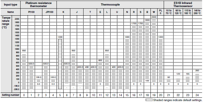
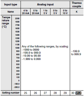
Shaded ranges indicate default settings.
Applicable standards by input type are as follows:
K, J, T, E, N, R, S, B: JIS C1602-1995, IEC584-1
L: Fe-CuNi, DIN 43710-1985
U: Cu-CuNi, DIN 43710-1985
W: W5Re/W26Re, ASTM E988-1990
PL II: According to Platinel II Electromotive Force Table by Engelhard Corp.
JPt100: JIS C 1604-1989, JIS C 1606-1989
Pt100: JIS C 1604-1997 IEC 751
HFU Unit/EJ1N-HFU[]-NFL[]
Ratings
| Power supply voltage | 24 VDC | |
|---|---|---|
| Operating voltage range | 85% to 110% of rated voltage | |
| Power consumption | 2 W max. (at maximum load) | |
| Auxiliary outputs * | Outputs | 4 |
| Transistor outputs | Max. operating voltage: 30 VDC, Max. load current: 50 mA | |
| Event inputs | Inputs | 4 |
| Contact inputs | ON: 1 kΩ max., OFF: 100 kΩ min. | |
| Transistor inputs | ON: residual voltage of 1.5 max., OFF: leakage current of 0.1 mA max. | |
| Event inputs | Outflow current: Approx. 4 mA (per contact) | |
| Programless connection | Downloading (EJ1 reads data from a PLC) | Number of parameters that can be set: 1200 [V1.2] |
| Uploading (EJ1 writes data to a PLC) | Number of parameters that can be set: 1200 [V1.2] | |
| Applicable PLCs | OMRON: CS/CJ/NJ Series Mitsubishi Electric: MELSEC-An/AnS/FX3UC Series [V1.1] Mitsubishi Electric: MELSEC-Q/QnA/QnAS Series | |
| Ambient temperature range | Operating: -10°C to 55°C Storage: -25°C to 65°C (with no icing or condensation) | |
| Ambient humidity range | Operating: 25% to 85% (with no condensation) | |
* Auxiliary outputs can be allocated using digital output allocations.
Characteristics
| Insulation resistance | 20 MΩ min. (at 500 VDC) | |
|---|---|---|
| Dielectric strength | 600 VAC, 50/60 Hz for 1 min between current-carrying terminals of different polarity | |
| Vibration resistance | 10 to 55 Hz, 20 m/s2 for 2 hours each in X, Y, and Z directions | |
| Shock resistance | 150 m/s2, 3 times each in 6 directions | |
| Weight | 160 g | |
| Degree of protection | Rear case: IP20, Terminal section: IP00 | |
| Memory protection | EEPROM (non-volatile memory) (number of writes: 100,000) | |
| Standards | Approved standards | UL61010C-1, CSA C22.2 No.1010-1 |
| EMC Directive | Refer to Catalog. | |
Communications Characteristics: Port C
| Transmission path connection | RS-485/RS-422: Multi-point, RS-232C: Point-to-point *1 |
|---|---|
| Communications method | RS-485/RS-422 (two-wire, half duplex), RS-232C |
| Synchronization method | Start-stop synchronization |
| Communications protocol | OMRON PLC protocol (Connectable PLCs: SYSMAC CS/CJ/CP Series) AnA/AnU CPU common commands (Connectable PLCs: MELSEC-An/AnS/FX3UC Series) [V1.1] MC protocol (form 5) (Connectable PLCs: MELSEC-Q/QnA/QnAS Series) |
| Baud rate | 9.6, 19.2, 38.4, 57.6, or 115.2 kbps |
| Transmission code | Binary |
| Data bit length | 8 bits |
| Stop bit length | 1 bit |
| Error detection | Depends on protocol selected for the programless communications protocol. |
| Flow control | None |
| Interface | RS-485, RS-422, RS-232C *1 |
| Retry function | Available |
| Communications response wait time | 0 to 99 ms (default: 5 ms) [V1.1] |
| Number of Basic Units that can be connected in parallel *2 | 32 Units (model numbers with TC4:128 channels max., model numbers with TC2:64 channels max.) |
| Number of HFUs that can be connected [V1.1] | CS/CJ/NJ-series PLCs: 8 (EJ1-HFU[]-NFLK) MELEC Q/QnA/QnAS-series PLCs: 8 (EJ1-HFU[]-NFL2) |
*1. The communications method can be switched between RS-485 and RS-232C. A separate model must be used for
RS-422 communications.
*2. For the number of Units that can be connected, refer to “Connection Precautions” on Catalog.
HFU Unit/EJ1N-HFUB-DRT
Ratings
| Power supply voltage | DeviceNet power supply | 24 VDC (for internal circuits) |
|---|---|---|
| EDU power supply | 24 VDC (for RS-485 communications circuits and Temperature Controllers) | |
| Operating voltage range | DeviceNet power supply | 11 to 25 VDC |
| EDU power supply | 20.4 to 26.4 VDC | |
| Power consumption (at maximum load) | 1 W max. (at maximum load) | |
| Main functions | Remote I/O communications, explicit message communications, CompoWay/F command feed-through function, parameter backup function, and configuration registration | |
| Ambient temperature range | Operating: -10°C to 55°C Storage: -25°C to 65°C (with no icing or condensation) | |
| Ambient humidity range | Operating: 25% to 85% (with no condensation) | |
Characteristics
| Insulation resistance | 20 MΩ min. (at 500 VDC) | |
|---|---|---|
| Dielectric strength | 600 VAC, 50/60 Hz for 1 min | |
| Vibration resistance | 10 to 55 Hz, 10 m/s2 for 2 hours each in X, Y, and Z directions | |
| Shock resistance | 150m/s2 max. 3 times each in 3 axes, 6 directions | |
| Weight | 70 g max. | |
| Degree of protection | IP20 | |
| Memory protection | EEPROM, 100,000 write operations (backup data) | |
| Standards | Approved standards | UL61010-1, CSA C22.2 No.1010-1 |
| EMC Directive | Refer to Catalog. | |
Communications Characteristics
| Communications protocol | Conforms to DeviceNet. | ||||
|---|---|---|---|---|---|
| Commu- nications functions | Remote I/O communications | Master-slave connections (polling, COS, or cyclic) Conforms to DeviceNet specifications. | |||
| I/O allocation | Input and output data can be allocated freely by user with the Configurator. Allocations can be made to DeviceNet parameters or Temperature Controller parameters. Two blocks for IN Area, up to 100 words One block for OUT Area, up to 100 words (The first word is always allocated to the OUT Enable Bit.) | ||||
| Message communications | Explicit message communications CompoWay/F communications commands can be sent (commands are sent in explicit message format). | ||||
| Connection format | Combination of multidrop and T-branch connections (for trunk and drop lines) | ||||
| Baud rate | DeviceNet: 500, 250, or 125 kbps, or automatic detection of master baud rate | ||||
| Communications media | Special 5-wire cable (2 signal lines, 2 power lines, and 1 shield line) | ||||
| Communications distance | Baud rate | Network length | Drop line length | Total drop line length | |
| 500 kbps | 100 m max. (100 m max.) | 6 m max. | 39 m max. | ||
| 250 kbps | 250 m max. (100 m max.) | 6 m max. | 78 m max. | ||
| 125 kbps | 500 m max. (100 m max.) | 6 m max. | 156 m max. | ||
| The values in parentheses apply when Thin Cables are used. | |||||
| Communications power supply | 11 to 25 VDC | ||||
| Maximum number of nodes that can be connected | 64 (includes Configurator when used.) | ||||
| Maximum number of slaves that can be connected | 63 | ||||
| Error control | CRC error detection | ||||
| DeviceNet power supply | Power supplied from DeviceNet communications connector | ||||
| Applicable Temperature Controllers | EJ1 Series (excluding the EJ1G) TC4: EJ1N-TC4A-QQ and EJ1N-TC4B-QQ TC2: EJ1N-TC2A-QNHB, EJ1N-TC2B-QNHB, EJ1N-TC2A-CNB, and EJ1N-TC2B-CNB | ||||
| Maximum number of Temperature Controllers that can be connected * | 16 Units (model numbers with TC4: 64 channels max., model numbers with TC2: 32 channels max.) | ||||
* For the number of Units that can be connected, refer to "Connection Precautions" on Catalog.
End Unit/EJ1C-EDU
Ratings
| Power supply voltage | 24 VDC | |
|---|---|---|
| Operating voltage range | 85% to 110% of rated voltage | |
| Auxiliary output * | Outputs | 2 |
| Transistor outputs | Max. operating voltage: 30 VDC, Max. load current: 50 mA | |
| Ambient temperature range | Operating: -10°C to 55°C Storage: -25°C to 65°C (with no icing or condensation) | |
| Ambient humidity range | Operating: 25% to 85% (with no condensation) | |
* Auxiliary output can be allocated using the bus output allocation for each Basic Unit.
Characteristics
| Insulation resistance | 20 MΩ min. (at 500 VDC) | |
|---|---|---|
| Dielectric strength | 600 VAC, 50/60 Hz for 1 min between current-carrying terminals of different polarity | |
| Vibration resistance | 10 to 55 Hz, 20 m/s2 for 2 hours each in X, Y, and Z directions | |
| Shock resistance | 150 m/s2, 3 times each in 6 directions | |
| Weight | 70 g | |
| Degree of protection | End Unit case: IP20, Terminal section: IP00 | |
| Standards | Approved standards | UL61010C-1, CSA C22.2 No.1010-1 |
| EMC Directive | Same as for the Basic Unit. Refer to Catalog. | |
Communications
| Port B *1 | Basic Unit Communications (Refer to "Communications Specifications" on Catalog.) |
|---|---|
| Port A | Basic Unit Communications (Refer to "Communications Specifications" on Catalog.) |
| Port A connector *2 | E58-CIFQ1 |
*1. Port B communications for the End Unit cannot be used when port C communications for the HFU is used.
*2. Port A connector communications and port A terminal communications cannot be used at the same time.
last update: December 09, 2015
OMRON EJ1 lineup
EJ1 Modular Temperature Controller/Lineuplast update: December 09, 2015
Temperature Controller
Standard Control Models
| Name | Power supply volt- age | No. of con- trol points | Con- trol out- puts 1 and 2 | Con- trol out- puts 3 and 4 | Aux- iliary out- put | Functions | Commu- nications functions | Input type | Ter- minal | Model | |
|---|---|---|---|---|---|---|---|---|---|---|---|
| Heater burn- out alarm | E- vent in- puts | ||||||||||
| Basic Unit (tem- perature control) *1 [V1.2] | 24 VDC supplied from the End Unit | 2 | Voltage output: 2 points (for SSR drive) *2 | Tran- sistor output: 2 points (sinking) | None | 2 *3 | 2 | G3ZA connection port: RS-485 From End Unit: Port A or port B: RS-485 | Thermo- couple, platinum resist- ance ther- mometer, analog voltage, and analog current selecta- ble for each channel. | M3 terminal | EJ1N-TC2A-QNHB |
| Screw- less clamp | EJ1N-TC2B-QNHB | ||||||||||
| 4 | Voltage output: 2 points (for SSR drive) *2 | None | None | M3 terminal | EJ1N-TC4A-QQ | ||||||
| Screw- less clamp | EJ1N-TC4B-QQ | ||||||||||
| 2 | Current output: 2 points | Tran- sistor output: 2 points (sinking) | 2 | M3 terminal | EJ1N-TC2A-CNB | ||||||
| Screw- less clamp | EJ1N-TC2B-CNB | ||||||||||
| HFU with Pro- gramless Commu- nications *1 [V1.2] | None | None | None | Tran- sistor output: 4 points (sinking) | 4 | Port C: RS-485 or RS-232C selectable. From End Unit: Port A: RS-485 | No input | M3 terminal | EJ1N-HFUA-NFLK | ||
| Screw- less clamp | EJ1N-HFUB-NFLK | ||||||||||
| Port C: RS-422 From End Unit: Port A: RS-485 | M3 terminal | EJ1N-HFUA-NFL2 | |||||||||
| Screw- less clamp | EJ1N-HFUB-NFL2 | ||||||||||
| HFU with DeviceNet Commu- nications *1 | None | None | DeviceNet communi- cations | Screw- less clamp | EJ1N-HFUB-DRT | ||||||
| End Unit *1 | 24 VDC | Tran- sistor output: 2 points (sinking) | None | Port A or B: RS-485 Connector: Port A | M3 terminal | EJ1C-EDUA-NFLK | |||||
| De- tachable con- nector | EJ1C-EDUC-NFLK | ||||||||||
*1. An End Unit is always required for connection to a Basic Unit or an HFU. An HFU cannot operate without a Basic Unit.
External communications cannot be performed when using a Basic Unit only.
*2. For heating/cooling control applications, control outputs 3 and 4 on the 2-point models are used for the cooling or
heating control outputs.
On the 4-point models, heating/cooling control is performed for the two input points.
*3. When using the heater burnout alarm, purchase a Current Transformer (E54-CT1 or E54-CT3) separately.
Note: Products for the EtherCAT master are also available. Ask your OMRON sales representative for details.
Functional Upgrades
Refer to Catalog for details.
Upgrade functions are supported by the indicated version ("V1.1" or "V1.2") or a higher version of the software.
Refer to the following manual for precautionary information and other information necessary to use the EJ1:
EJ1 Modular Temperature Controller User’s Manual (Cat. No. H142)
EtherCAT® is registered trademark and patented technology, licensed by Beckhoff Automation GmbH, Germany.
Accessories (Order Separately)
Current Transformer (CT)
| Diameter | Model |
|---|---|
| 5.8 dia. | E54-CT1 |
| 12.0 dia. | E54-CT3 |
G3ZA Connecting Cable
| Cable length | Model |
|---|---|
| 5 m | EJ1C-CBLA050 |
Rail Mounting Equipment
| Name | Model |
|---|---|
| Mounting Rail | PFP-100N |
| PFP-50N |
CX-Thermo Support Software Ver. 4.1
| Model |
|---|
| EST2-2C-MV4 |
USB-Serial Conversion Cable
| Model |
|---|
| E58-CIFQ1 |
last update: December 09, 2015
OMRON EJ1 catalog
EJ1 Modular Temperature Controller/Catalog- Catalog
- Manual
- CAD
English
Global Edition
| Catalog Name | Catalog Number [size] | Last Update | |
|---|---|---|---|
| | - [4241KB] | Apr 02, 201820180402 | EJ1 Data Sheet |
OMRON EJ1 dimension
EJ1 Modular Temperature Controller/Dimensionslast update: August 22, 2013
Temperature Controller
Basic Units
EJ1N-TC
HFUs
EJ1N-HFU[]-NFL[]
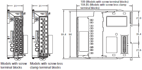
HFUs
EJ1N-HFUB-DRT
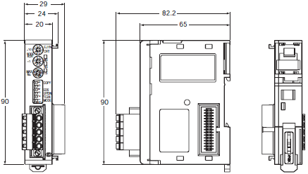
End Units
EJ1C-EDU
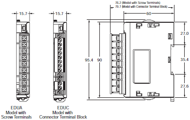
Options
Current Transformer
E54-CT1
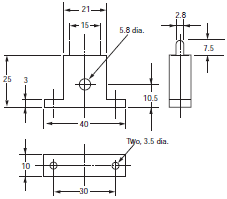
E54-CT3
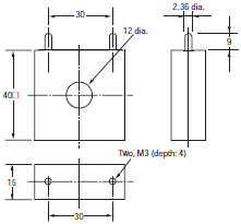
E54-CT3 Accessory
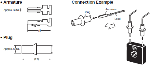
Rail Mounting Equipment (Order Separately)
DIN Rail
PFP-100N
PFP-50N

* The figures in parentheses are dimensions for the PFP-50N.
End Plate
PFP-M
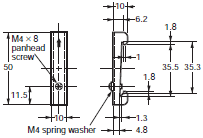
Note: Two screws are included with the EJ1C-EDU for the End Plate.
Always attach End Plates to both sides.
last update: August 22, 2013
- NO. EJ1
- TYPE:Temperature Controllers Module Type
 Copyright Statement
 - DATE:2021-06-14
- Associated products:
E5L Electronic Thermostat/Features E5ZN Modular Temperature Controller/Features