
OMRON S8FS-GPower Supplies / In Addition/ Power Supplies/Switch mode power supplies
OMRON S8FS-G Power Supplies / In Addition
- S8FS-G Switch Mode Power Supply (15/30/50/100/150/300/600-W Models)/Catalog
- S8FS-G Switch Mode Power Supply (15/30/50/100/150/300/600-W Models)/Lineup
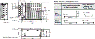
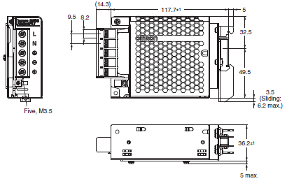
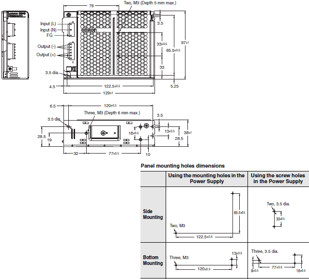
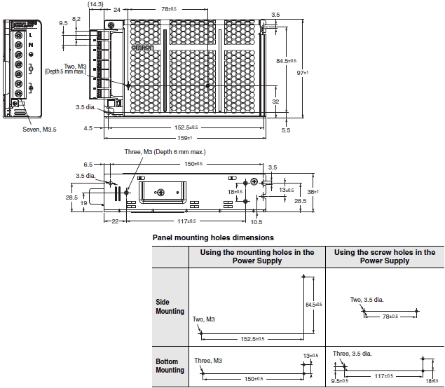
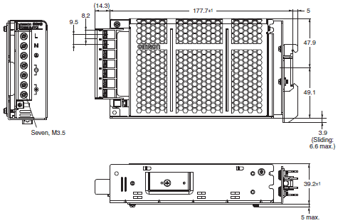
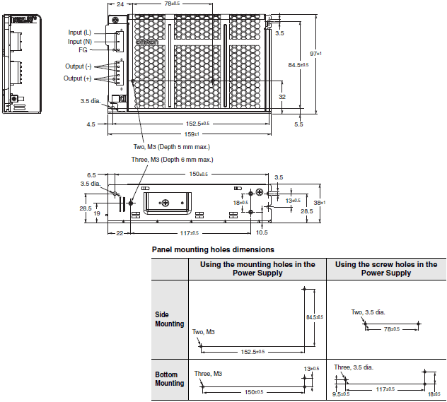
- S8FS-G Switch Mode Power Supply (15/30/50/100/150/300/600-W Models)/Dimensions
- S8FS-G Switch Mode Power Supply (15/30/50/100/150/300/600-W Models)/Specifications
- Purchase the OMRON S8FS-G Switch mode power supplies
OMRON S8FS-G Dimensions
/Images/l_3656-25-271451-198x198.jpglast update: December 1, 2016
Power Supplies That Are Ideal for Machine Tools and Semiconductor Manufacturing Equipment
No Transformers Required for Control Circuits
Built-in IEC 61558-2-16 Compliant Transformer
An IEC 61558-2-16 compliant transformer is built into the Power Supply to eliminate the need for a transformer with compound windings for control circuits for which IEC 60204-1 Machinery Directive is specified. This helps reduce cost and space requirements.

Easy Safety Standard Certification
All Normal Stock Models Are UL 508 Listed *
1. Less work is required to prepare data and materials for UL application.
2. Connection is possible to devices or equipment outside the control panel.
* Some optional models are UL recognized. (Excluding models with connectors.)

Equipment Downsizing
Slim Body of 300-/600-W models

Stable Operation in a Wide Range of Environments
Resistance to Environments for Global Application
Stable operation in severe installation environments, such as those with high ambient temperatures and humidity, or large vibration or those with unstable input voltages.

Prevention of Foreign Matter Ingress and Screw Drop Out
The front cover prevents entry of foreign matter from the front surface.
A removable mechanism that prevents terminal block screws from dropping out is a standard feature.
You can prevent foreign matter ingress and screw drop out that can result in product failure and accidents for worry-free installation and maintenance work.

Stable, High Quality
75% of all the manufacturing processes have been mechanized.
We have also mechanized inspection and confirmation processes.

last update: December 1, 2016
Purchase the OMRON Switch mode power supplies Please fill in the following
If you have just landed here, this product OMRON S8FS-G Power Supplies / In Addition,Power Supplies / In Addition is offered online by Tianin FLD Technical Co.,Ltd. This is an online store providing Power Supplies / In Addition at wholesale prices for consumers. You can call us or send enquiry, we would give you the prices, packing,deliverty and more detailed information on the S8FS-G We cooperate with DHL,TNT,FEDEX,UPS,EMS,etc.They guarantee to meet your needs in terms of time and money,even if you need your OMRON S8FS-GPower Supplies / In Addition tomorrow morning (aka overnight or next day air) on your desk, 2, 3 days or more.Note to international customers, YES, we ship worldwide.
NT11 / NT21 Programmable Terminals/Features
D4JL, D4JL-SK40 Guard Lock Safety-door Switch/Slide key/Features
G3F / G3FD Solid State Relays G3[]-VD/Features
DCA2 / DCN3 / XS4 DeviceNet Connectors with Thick Cables/Features
S8FS-G Switch Mode Power Supply (15/30/50/100/150/300/600-W Models)/Features
OMRON S8FS-G catalog
S8FS-G Switch Mode Power Supply (15/30/50/100/150/300/600-W Models)/Catalog- Catalog
- Manual
- CAD
English
Global Edition
| Catalog Name | Catalog Number [size] | Last Update | |
|---|---|---|---|
| | T207-E1-03 [7456KB] | Jan 07, 201920190107 | S8FS-G Data Sheet |
| | T208-E1-01 [774KB] | Dec 01, 201620161201 | S8FS-G Catalog |
| | T209-E1-01 [2003KB] | Aug 27, 201820180827 | S8VK-S/S8FS-G Power Supply Guide Catalog |
| | T216-E1-01 [4336KB] | Aug 09, 201820180809 | S8JX-N/S8JX-G Series Replacement Brackets |
| | T217-E1-01 [4233KB] | Aug 09, 201820180809 | S8JX-P Series Replacement Brackets |
| | T218-E1-01 [6407KB] | Aug 09, 201820180809 | S8VM Series Replacement Brackets |
OMRON S8FS-G lineup
S8FS-G Switch Mode Power Supply (15/30/50/100/150/300/600-W Models)/Lineuplast update: May 14, 2018
Lineup
| Output voltage | Power rating | ||||||
|---|---|---|---|---|---|---|---|
| 15 W | 30 W | 50 W | 100 W | 150 W | 300 W | 600 W | |
| 5 V | Yes | Yes | Yes | Yes | Yes | --- | --- |
| 12 V | Yes | Yes | Yes | Yes | Yes | Yes | Yes |
| 15 V | Yes | Yes | Yes | Yes | Yes | Yes | Yes |
| 24 V | Yes | Yes | Yes | Yes | Yes | Yes | Yes |
| 48 V | --- | --- | --- | --- | Yes | Yes | Yes |
Model Number Structure
Model Number Legend
Note: Not all combinations are possible. Refer to List of Models in Ordering Information, below.

Ordering Information
List of Models
Note: For details on normal stock models, contact your nearest OMRON representative.
With Cover/Direct Mounting
| Power ratings | Input voltage | Output voltage (VDC) | Output current | Built-in fan | Model |
|---|---|---|---|---|---|
| 15 W | 100 to 240 VAC (Permissible range 85 to 264 VAC, 80 to 370 VDC) *4 | 5 V | 3 A | None | S8FS-G01505C |
| 12 V | 1.3 A | S8FS-G01512C | |||
| 15 V | 1 A | S8FS-G01515C | |||
| 24 V | 0.65 A | S8FS-G01524C | |||
| 30 W | 5 V | 6 A | S8FS-G03005C | ||
| 12 V | 3 A | S8FS-G03012C | |||
| 15 V | 2.4 A | S8FS-G03015C | |||
| 24 V | 1.5 A | S8FS-G03024C | |||
| 50 W | 5 V | 8 A *1 | S8FS-G05005C | ||
| 12 V | 4.3 A | S8FS-G05012C | |||
| 15 V | 3.5 A | S8FS-G05015C | |||
| 24 V | 2.2 A | S8FS-G05024C | |||
| 100 W | 5 V | 16 A *2 | S8FS-G10005C | ||
| 12 V | 8.5 A | S8FS-G10012C | |||
| 15 V | 7 A | S8FS-G10015C | |||
| 24 V | 4.5 A | S8FS-G10024C | |||
| 150 W | 5 V | 21 A *3 | S8FS-G15005C | ||
| 12 V | 13 A | S8FS-G15012C | |||
| 15 V | 10 A | S8FS-G15015C | |||
| 24 V | 6.5 A | S8FS-G15024C | |||
| 48 V | 3.3 A | S8FS-G15048C | |||
| 300 W | 100 to 240 VAC (Permissible range 85 to 264 VAC, 120 to 370 VDC) | 12 V | 25 A | Yes | S8FS-G30012C |
| 15 V | 20 A | S8FS-G30015C | |||
| 24 V | 14 A | S8FS-G30024C | |||
| 48 V | 7 A | S8FS-G30048C | |||
| 600 W | 100 to 240 VAC (Permissible range 85 to 264 VAC, 120 to 350 VDC) | 12 V | 50 A | S8FS-G60012C | |
| 15 V | 40 A | S8FS-G60015C | |||
| 24 V | 27 A | S8FS-G60024C | |||
| 48 V | 13 A | S8FS-G60048C |
Note: 1. Ask your OMRON representative for pricing information on optional models.
2. Front-mounting is not possible.
To mount a Power Supply from the front, purchase a DIN Rail-mounting Power Supply and a Front-mounting
Bracket (sold separately). Refer to Data Sheet.
With Cover/Direct Mounting (Extended hold time type)
| Power ratings | Input voltage | Output voltage (VDC) | Output current | Built-in fan | Model |
|---|---|---|---|---|---|
| 300 W | 100 to 240 VAC (Permissible range 85 to 264 VAC, 120 to 370 VDC) | 24 V | 14 A | Yes | S8FS-G30024C-H |
| 600 W | 100 to 240 VAC (Permissible range 85 to 264 VAC, 120 to 350 VDC) | 27 A | S8FS-G60024C-H |
With Cover/Direct Mounting (Connector type)
| Power ratings | Input voltage | Output voltage (VDC) | Output current | Built-in fan | Model |
|---|---|---|---|---|---|
| 15 W | 100 to 240 VAC (Permissible range 85 to 264 VAC, 80 to 370 VDC) *4 | 24 V | 0.65 A | None | S8FS-G01524CE |
| 30 W | 1.5 A | S8FS-G03024CE | |||
| 50 W | 2.2 A | S8FS-G05024CE | |||
| 100 W | 4.5 A | S8FS-G10024CE | |||
| 150 W | 6.5 A | S8FS-G15024CE |
*1. The output electric power is 40 W.
*2. The output electric power is 80 W.
*3. The output electric power is 105 W.
*4. Applicable to products produced from May 2018.
With Cover/DIN Rail Mounting
| Power ratings | Input voltage | Output voltage (VDC) | Output current | Built-in fan | Model |
|---|---|---|---|---|---|
| 15 W | 100 to 240 VAC (Permissible range 85 to 264 VAC, 80 to 370 VDC) *4 | 5 V | 3 A | None | S8FS-G01505CD |
| 12 V | 1.3 A | S8FS-G01512CD | |||
| 15 V | 1 A | S8FS-G01515CD | |||
| 24 V | 0.65 A | S8FS-G01524CD | |||
| 30 W | 5 V | 6 A | S8FS-G03005CD | ||
| 12 V | 3 A | S8FS-G03012CD | |||
| 15 V | 2.4 A | S8FS-G03015CD | |||
| 24 V | 1.5 A | S8FS-G03024CD | |||
| 50 W | 5 V | 8 A *1 | S8FS-G05005CD | ||
| 12 V | 4.3 A | S8FS-G05012CD | |||
| 15 V | 3.5 A | S8FS-G05015CD | |||
| 24 V | 2.2 A | S8FS-G05024CD | |||
| 100 W | 5 V | 16 A *2 | S8FS-G10005CD | ||
| 12 V | 8.5 A | S8FS-G10012CD | |||
| 15 V | 7 A | S8FS-G10015CD | |||
| 24 V | 4.5 A | S8FS-G10024CD | |||
| 150 W | 5 V | 21 A *3 | S8FS-G15005CD | ||
| 12 V | 13 A | S8FS-G15012CD | |||
| 15 V | 10 A | S8FS-G15015CD | |||
| 24 V | 6.5 A | S8FS-G15024CD | |||
| 48 V | 3.3 A | S8FS-G15048CD | |||
| 300 W | 100 to 240 VAC (Permissible range 85 to 264 VAC, 120 to 370 VDC) | 12 V | 25 A | Yes | S8FS-G30012CD |
| 15 V | 20 A | S8FS-G30015CD | |||
| 24 V | 14 A | S8FS-G30024CD | |||
| 48 V | 7 A | S8FS-G30048CD | |||
| 600 W | 100 to 240 VAC (Permissible range 85 to 264 VAC, 120 to 350 VDC) | 12 V | 50 A | S8FS-G60012CD | |
| 15 V | 40 A | S8FS-G60015CD | |||
| 24 V | 27 A | S8FS-G60024CD | |||
| 48 V | 13 A | S8FS-G60048CD |
Note: Ask your OMRON representative for pricing information on optional models.
*1. The output electric power is 40 W.
*2. The output electric power is 80 W.
*3. The output electric power is 105 W.
*4. Applicable to products produced from May 2018.
With Cover/DIN Rail Mounting (Extended hold time type)
| Power ratings | Input voltage | Output voltage (VDC) | Output current | Built-in fan | Model |
|---|---|---|---|---|---|
| 300 W | 100 to 240 VAC (Permissible range 85 to 264 VAC, 120 to 370 VDC) | 24 V | 14 A | Yes | S8FS-G30024CD-H |
| 600 W | 100 to 240 VAC (Permissible range 85 to 264 VAC, 120 to 350 VDC) | 27 A | S8FS-G60024CD-H |
Mounting Brackets (Order Separately)
Use the Front-mounting Brackets together with DIN Rail-mounting Power Supplies (S8FS-G[][][][][]CD).
| Power rating | Mounting direction | Model |
|---|---|---|
| 15 W, 30 W, 50 W, 100 W, 150 W and 300 W | Front-mounting | S82Y-FSG-30F |
| 600 W | Front-mounting | S82Y-FSG-60F |
Terminal cover (Order Separately)
| Power rating | Applicable models | Terminal Cover model number |
|---|---|---|
| 15 W | S8FS-G015[][][] | S82Y-FSG-C5P |
| 30 W | S8FS-G030[][][] | |
| 50 W | S8FS-G050[][][] | |
| 100 W | S8FS-G100[][][] | S82Y-FSG-C7P |
| 150 W | S8FS-G150[][][] | |
| 300 W | S8FS-G300[][][] | |
| 600 W | S8FS-G600[][][] | S82Y-FSG-C7P-L (Input Output) |
Note: A Terminal Block Cover is provided with the Power Supply as a standard accessory. You can purchase another one
if your Cover is damaged or lost.
last update: May 14, 2018
OMRON S8FS-G dimension
S8FS-G Switch Mode Power Supply (15/30/50/100/150/300/600-W Models)/Dimensionslast update: January 7, 2019
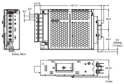
(Unit: mm)
Power Supplies
15 W and 30 W
S8FS-G015[][]C
S8FS-G030[][]C
S8FS-G015[][]CD
S8FS-G030[][]CD
S8FS-G015[][]E
S8FS-G030[][]E
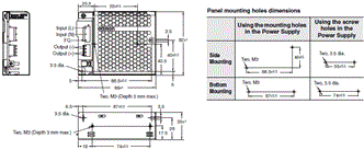
50 W
S8FS-G050[][]C
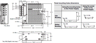
S8FS-G050[][]CD
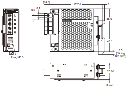
S8FS-G050[][]E
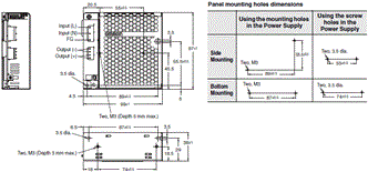
100 W
S8FS-G100[][]C
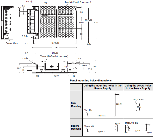
S8FS-G100[][]CD
S8FS-G100[][]E
150 W
S8FS-G150[][]C
S8FS-G150[][]CD
S8FS-G150[][]E
300 W
S8FS-G300[][]C
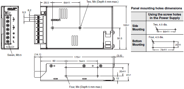
S8FS-G300[][]CD
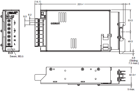
Note: Use a metal DIN Rail when mounting a 300-W model to a DIN Rail.
600 W
S8FS-G600[][]C
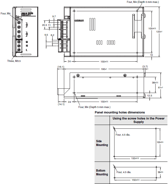
S8FS-G600[][]CD
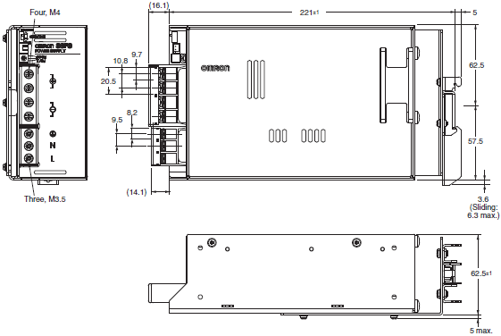
Note: Use a metal DIN Rail when mounting a 600-W model to a DIN Rail.
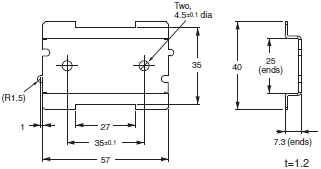
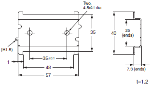
Mounting Brackets (Order Separately)
Use the Front-mounting Brackets together with DIN Rail-mounting Power Supplies (S8FS-G[][][][][]CD).
S82Y-FSG-30F
S82Y-FSG-60F
Note: Replacement brackets from the S8JX-N, S8JX-P, and S8VM series are available.
Refer to the data sheet (Cat. No.: T216-E1, T217-E1, and T218-E1) for more information.
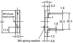
DIN Rail (Order Separately)
Mounting Rail (Material: Aluminum)
PFP-100N
PFP-50N

PFP-100N2

End Plate
PFP-M
Note: If there is a possibility that the Unit will be subject to vibration or shock, use a steel DIN Rail. Otherwise, metallic
filings may result from aluminum abrasion.
last update: January 7, 2019
OMRON S8FS-G specification
S8FS-G Switch Mode Power Supply (15/30/50/100/150/300/600-W Models)/Specificationslast update: May 14, 2018
Specifications
| Power rating | 15 W | |||||
|---|---|---|---|---|---|---|
| Output voltage | 5 V | 12 V | 15 V | 24 V | ||
| Efficiency * | 100 VAC input | 80% typ. | 84% typ. | 84% typ. | 85% typ. | |
| 200 VAC input | 80% typ. | 84% typ. | 84% typ. | 86% typ. | ||
| 230 VAC input | 80% typ. | 84% typ. | 84% typ. | 86% typ. | ||
| Input | Voltage range * | Single phase, 85 to 264 VAC, 80 to 370 VDC | ||||
| Frequency * | 50/60 Hz (47 to 450 Hz) | |||||
| Current * | 100 VAC input | 0.32 A typ. | ||||
| 200 VAC input | 0.2 A typ. | |||||
| Power factor | --- | |||||
| Leakage current * | 100 VAC input | 0.5 mA max. | ||||
| 200 VAC input | 1 mA max. | |||||
| Inrush current * (for a cold start at 25°C) | 100 VAC input | 14 A typ. | ||||
| 200 VAC input | 28 A typ. | |||||
| Output | Rated Output Current | 3 A | 1.3 A | 1 A | 0.65 A | |
| Voltage adjustment range * | -10% to 15% (with V.ADJ) | |||||
| Ripple & Noise voltage * | 100 to 240 VAC input | 40 mVp-p max. | 40 mVp-p max. | 40 mVp-p max. | 60 mVp-p max. | |
| Input variation influence * | 0.5% max. | |||||
| Load variation influence * | 1.0% max. | |||||
| Temperature variation influence | 100 to 240 VAC input | 0.05%/°C max. | ||||
| Startup time * | 100 VAC input | 1,000 ms max. | ||||
| 200 VAC input | 1,000 ms max. | |||||
| Hold time * | 100 VAC input | 15 ms typ. | 14 ms typ. | 15 ms typ. | 15 ms typ. | |
| 200 VAC input | 75 ms typ. | 70 ms typ. | 75 ms typ. | 70 ms typ. | ||
| Additional functions | Overload protection | Yes, automatic reset | ||||
| Overvoltage protection * | Yes, 120% or higher of rated output voltage, power shut off (shut off the input voltage and turn on the input again) | |||||
| Overheat protection | No | |||||
| Series operation | Yes (For up to two Power Supplies, external diodes are required.) | |||||
| Parallel operation | No (However, backup operation is possible, external diodes are required.) | |||||
| Remote sensing | No | |||||
| Remote control | No | |||||
| Output indicator | Yes (LED: Green) | |||||
| Insulation | Withstand voltage | 3 kVAC for 1 min. (between all input terminals and output terminals) current cutoff 20 mA | ||||
| 2 kVAC for 1 min. (between all input terminals and PE terminals) current cutoff 20 mA | ||||||
| 1 kVAC for 1 min. (between all output terminals and PE terminals) current cutoff 20 mA | ||||||
| Insulation resistance | 100 MΩ min. (between all output terminals and all input terminals/PE terminals) at 500 VDC | |||||
| Environ- ment | Ambient operating temperature | -20 to 70°C (Derating is required according to the temperature.) (with no condensation or icing) | ||||
| Storage temperature | -25 to 75°C (with no condensation or icing) | |||||
| Ambient operating humidity | 90% max. (Storage humidity: 90% max.) | |||||
| Vibration resistance | 10 to 55 Hz, 4.5 G max., 0.375-mm half amplitude for 2 h each in X, Y, and Z directions | |||||
| Shock resistance | 150 m/s2, 3 times each in ±X, ±Y, ±Z directions | |||||
| Reliability | MTBF | 135,000 hrs min. | ||||
| Life expectancy * | 10 years min. | |||||
| Con- struction | Dimensions (W×H×D) | Refer to Dimensions. | ||||
| Weight | 250 g | |||||
| Cooling fan | No | |||||
| Degree of protection | --- | |||||
| Standards | Harmonic current emissions | Conforms to EN 61000-3-2 | ||||
| EMI * | Conducted Emissions | Conforms to EN 61204-3 Class B, EN 55011 Class B | ||||
| Radiated Emissions | Conforms to EN 61204-3 Class B, EN 55011 Class B | |||||
| EMS | Conforms to EN 61204-3 high severity levels | |||||
| Safety Standards | UL 508 (Listing, excluding models with connector option) UL 60950-1, UL 62368-1 (Recognition, OVCII [≤ 3,000 m], Pol2) CSA C22.2 No.107.1 (excluding models with connector option) CSA C22.2 No.60950-1, No.62368-1 (excluding models with connector option) EN 50178 (OVCIII [≤ 2,000 m], OVCII [> 2,000 m and ≤ 3,000 m], Pol2) EN/IEC 60950-1, EN/IEC 62368-1 (OVCII [≤ 3,000 m], Pol2) Conforms to EN/IEC 61558-2-16 Conforms to PELV (EN/IEC 60204-1) | |||||
| Marine Standards | No | |||||
| SEMI | Conforms to F47-0706 (200 VAC input) | |||||
* Refer to Ratings, Characteristics, and Functions below.
| Power rating | 30 W | |||||
|---|---|---|---|---|---|---|
| Output voltage | 5 V | 12 V | 15 V | 24 V | ||
| Efficiency * | 100 VAC input | 81% typ. | 84% typ. | 86% typ. | 86% typ. | |
| 200 VAC input | 81% typ. | 86% typ. | 88% typ. | 88% typ. | ||
| 230 VAC input | 81% typ. | 86% typ. | 88% typ. | 89% typ. | ||
| Input | Voltage range * | Single phase, 85 to 264 VAC, 80 to 370 VDC | ||||
| Frequency * | 50/60 Hz (47 to 450 Hz) | |||||
| Current * | 100 VAC input | 0.72 A typ. | ||||
| 200 VAC input | 0.43 A typ. | |||||
| Power factor | --- | |||||
| Leakage current * | 100 VAC input | 0.5 mA max. | ||||
| 200 VAC input | 1 mA max. | |||||
| Inrush current * (for a cold start at 25°C) | 100 VAC input | 14 A typ. | ||||
| 200 VAC input | 28 A typ. | |||||
| Output | Rated Output Current | 6 A | 3 A | 2.4 A | 1.5 A | |
| Voltage adjustment range * | -10% to 15% (with V.ADJ) | |||||
| Ripple & Noise voltage * | 100 to 240 VAC input | 50 mVp-p max. | 60 mVp-p max. | 50 mVp-p max. | 60 mVp-p max. | |
| Input variation influence * | 0.5% max. | |||||
| Load variation influence * | 1.0% max. | |||||
| Temperature variation influence | 100 to 240 VAC input | 0.05%/°C max. | ||||
| Startup time * | 100 VAC input | 1,000 ms max. | ||||
| 200 VAC input | 1,000 ms max. | |||||
| Hold time * | 100 VAC input | 11 ms typ. | 10 ms typ. | 11 ms typ. | 10 ms typ. | |
| 200 VAC input | 60 ms typ. | 50 ms typ. | 50 ms typ. | 55 ms typ. | ||
| Additional functions | Overload protection | Yes, automatic reset | ||||
| Overvoltage protection * | Yes, 120% or higher of rated output voltage, power shut off (shut off the input voltage and turn on the input again) | |||||
| Overheat protection | No | |||||
| Series operation | Yes (For up to two Power Supplies, external diodes are required.) | |||||
| Parallel operation | No (However, backup operation is possible, external diodes are required.) | |||||
| Remote sensing | No | |||||
| Remote control | No | |||||
| Output indicator | Yes (LED: Green) | |||||
| Insulation | Withstand voltage | 3 kVAC for 1 min. (between all input terminals and output terminals) current cutoff 20 mA | ||||
| 2 kVAC for 1 min. (between all input terminals and PE terminals) current cutoff 20 mA | ||||||
| 1 kVAC for 1 min. (between all output terminals and PE terminals) current cutoff 20 mA | ||||||
| Insulation resistance | 100 MΩ min. (between all output terminals and all input terminals/PE terminals) at 500 VDC | |||||
| Environ- ment | Ambient operating temperature | -20 to 70°C (Derating is required according to the temperature.) (with no condensation or icing) | ||||
| Storage temperature | -25 to 75°C (with no condensation or icing) | |||||
| Ambient operating humidity | 90% max. (Storage humidity: 90% max.) | |||||
| Vibration resistance | 10 to 55 Hz, 4.5 G max., 0.375-mm half amplitude for 2 h each in X, Y, and Z directions | |||||
| Shock resistance | 150 m/s2, 3 times each in ±X, ±Y, ±Z directions | |||||
| Reliability | MTBF | 135,000 hrs min. | ||||
| Life expectancy * | 10 years min. | |||||
| Con- struction | Dimensions (W×H×D) | Refer to Dimensions. | ||||
| Weight | 250 g | |||||
| Cooling fan | No | |||||
| Degree of protection | --- | |||||
| Standards | Harmonic current emissions | Conforms to EN 61000-3-2 | ||||
| EMI * | Conducted Emissions | Conforms to EN 61204-3 Class B, EN 55011 Class B | ||||
| Radiated Emissions | Conforms to EN 61204-3 Class B, EN 55011 Class B | |||||
| EMS | Conforms to EN 61204-3 high severity levels | |||||
| Safety Standards | UL 508 (Listing, excluding models with connector option) UL 60950-1, UL 62368-1 (Recognition, OVCII [≤ 3,000 m], Pol2) CSA C22.2 No.107.1 (excluding models with connector option) CSA C22.2 No.60950-1, No.62368-1 (excluding models with connector option) EN 50178 (OVCIII [≤ 2,000 m], OVCII [> 2,000 m and ≤ 3,000 m], Pol2) EN/IEC 60950-1, EN/IEC 62368-1 (OVCII [≤ 3,000 m], Pol2) Conforms to EN/IEC 61558-2-16 Conforms to PELV (EN/IEC 60204-1) | |||||
| Marine Standards | No | |||||
| SEMI | Conforms to F47-0706 (200 VAC input) | |||||
* Refer to Ratings, Characteristics, and Functions below.
| Power rating | 50 W | |||||
|---|---|---|---|---|---|---|
| Output voltage | 5 V | 12 V | 15 V | 24 V | ||
| Efficiency * | 100 VAC input | 81% typ. | 84% typ. | 86% typ. | 86% typ. | |
| 200 VAC input | 82% typ. | 86% typ. | 88% typ. | 89% typ. | ||
| 230 VAC input | 82% typ. | 86% typ. | 88% typ. | 89% typ. | ||
| Input | Voltage range * | Single phase, 85 to 264 VAC, 80 to 370 VDC | ||||
| Frequency * | 50/60 Hz (47 to 450 Hz) | |||||
| Current * | 100 VAC input | 1.1 A typ. | ||||
| 200 VAC input | 0.62 A typ. | |||||
| Power factor | --- | |||||
| Leakage current * | 100 VAC input | 0.5 mA max. | ||||
| 200 VAC input | 1 mA max. | |||||
| Inrush current * (for a cold start at 25°C) | 100 VAC input | 14 A typ. | ||||
| 200 VAC input | 28 A typ. | |||||
| Output | Rated Output Current | 8 A | 4.3 A | 3.5 A | 2.2A | |
| Voltage adjustment range * | -10% to 15% (with V.ADJ) | |||||
| Ripple & Noise voltage * | 100 to 240 VAC input | 40 mVp-p max. | 40 mVp-p max. | 40 mVp-p max. | 60 mVp-p max. | |
| Input variation influence * | 0.5% max. | |||||
| Load variation influence * | 1.0% max. | |||||
| Temperature variation influence | 100 to 240 VAC input | 0.05%/°C max. | ||||
| Startup time * | 100 VAC input | 1,000 ms max. | ||||
| 200 VAC input | 1,000 ms max. | |||||
| Hold time * | 100 VAC input | 14 ms typ. | 11 ms typ. | 10 ms typ. | 10 ms typ. | |
| 200 VAC input | 75 ms typ. | 60 ms typ. | 60 ms typ. | 55 ms typ. | ||
| Additional functions | Overload protection | Yes, automatic reset | ||||
| Overvoltage protection * | Yes, 120% or higher of rated output voltage, power shut off (shut off the input voltage and turn on the input again) | |||||
| Overheat protection | No | |||||
| Series operation | Yes (For up to two Power Supplies, external diodes are required.) | |||||
| Parallel operation | No (However, backup operation is possible, external diodes are required.) | |||||
| Remote sensing | No | |||||
| Remote control | No | |||||
| Output indicator | Yes (LED: Green) | |||||
| Insulation | Withstand voltage | 3 kVAC for 1 min. (between all input terminals and output terminals) current cutoff 20 mA | ||||
| 2 kVAC for 1 min. (between all input terminals and PE terminals) current cutoff 20 mA | ||||||
| 1 kVAC for 1 min. (between all output terminals and PE terminals) current cutoff 20 mA | ||||||
| 500 VAC for 1 min. (between all output terminals and RC terminals) current cutoff 20 mA | ||||||
| Insulation resistance | 100 MΩ min. (between all output terminals and all input terminals/PE terminals) at 500 VDC | |||||
| Environ- ment | Ambient operating temperature | -20 to 70°C (Derating is required according to the temperature.) (with no condensation or icing) | ||||
| Storage temperature | -25 to 75°C (with no condensation or icing) | |||||
| Ambient operating humidity | 90% max. (Storage humidity: 90% max.) | |||||
| Vibration resistance | 10 to 55 Hz, 4.5 G max., 0.375-mm half amplitude for 2 h each in X, Y, and Z directions | |||||
| Shock resistance | 150 m/s2, 3 times each in ±X, ±Y, ±Z directions | |||||
| Reliability | MTBF | 135,000 hrs min. | ||||
| Life expectancy * | 10 years min. | |||||
| Con- struction | Dimensions (W×H×D) | Refer to Dimensions. | ||||
| Weight | 300 g | |||||
| Cooling fan | No | |||||
| Degree of protection | --- | |||||
| Standards | Harmonic current emissions | Conforms to EN 61000-3-2 | ||||
| EMI * | Conducted Emissions | Conforms to EN 61204-3 Class B, EN 55011 Class B | ||||
| Radiated Emissions | Conforms to EN 61204-3 Class B, EN 55011 Class B | |||||
| EMS | Conforms to EN 61204-3 high severity levels | |||||
| Safety Standards | UL 508 (Listing, excluding models with connector option) UL 60950-1, UL 62368-1 (Recognition, OVCII [≤ 3,000 m], Pol2) CSA C22.2 No.107.1 (excluding models with connector option) CSA C22.2 No.60950-1, No.62368-1 (excluding models with connector option) EN 50178 (OVCIII [≤ 2,000 m], OVCII [> 2,000 m and ≤ 3,000 m], Pol2) EN/IEC 60950-1, EN/IEC 62368-1 (OVCII [≤ 3,000 m], Pol2) Conforms to EN/IEC 61558-2-16 Conforms to PELV (EN/IEC 60204-1) | |||||
| Marine Standards | No | |||||
| SEMI | Conforms to F47-0706 (200 VAC input) | |||||
* Refer to Ratings, Characteristics, and Functions below.
| Power rating | 100 W | |||||
|---|---|---|---|---|---|---|
| Output voltage | 5 V | 12 V | 15 V | 24 V | ||
| Efficiency * | 100 VAC input | 79% typ. | 84% typ. | 85% typ. | 87% typ. | |
| 200 VAC input | 81% typ. | 86% typ. | 87% typ. | 89% typ. | ||
| 230 VAC input | 81% typ. | 86% typ. | 87% typ. | 89% typ. | ||
| Input | Voltage range * | Single phase, 85 to 264 VAC, 80 to 370 VDC | ||||
| Frequency * | 50/60 Hz (47 to 450 Hz) | |||||
| Current * | 100 VAC input | 2.1 A typ. | ||||
| 200 VAC input | 1.2 A typ. | |||||
| Power factor | --- | |||||
| Leakage current * | 100 VAC input | 0.5 mA max. | ||||
| 200 VAC input | 1 mA max. | |||||
| Inrush current * (for a cold start at 25°C) | 100 VAC input | 14 A typ. | ||||
| 200 VAC input | 28 A typ. | |||||
| Output | Rated Output Current | 16 A | 8.5 A | 7 A | 4.5 A | |
| Voltage adjustment range * | -10% to 15% (with V.ADJ) | |||||
| Ripple & Noise voltage * | 100 to 240 VAC input | 70 mVp-p max. | 90 mVp-p max. | 100 mVp-p max. | 80 mVp-p max. | |
| Input variation influence * | 0.5% max. | |||||
| Load variation influence * | 1.0% max. | |||||
| Temperature variation influence | 100 to 240 VAC input | 0.05%/°C max. | ||||
| Startup time * | 100 VAC input | 1,000 ms max. | ||||
| 200 VAC input | 1,000 ms max. | |||||
| Hold time * | 100 VAC input | 12 ms typ. | 11 ms typ. | 11 ms typ. | 10 ms typ. | |
| 200 VAC input | 70 ms typ. | 55 ms typ. | 55 ms typ. | 55 ms typ. | ||
| Additional functions | Overload protection | Yes, automatic reset | ||||
| Overvoltage protection * | Yes, 120% or higher of rated output voltage, power shut off (shut off the input voltage and turn on the input again) | |||||
| Overheat protection | No | |||||
| Series operation | Yes (For up to two Power Supplies, external diodes are required.) | |||||
| Parallel operation | No (However, backup operation is possible, external diodes are required.) | |||||
| Remote sensing | No | |||||
| Remote control | Yes (Only for models with remote control option) | |||||
| Output indicator | Yes (LED: Green) | |||||
| Insulation | Withstand voltage | 3 kVAC for 1 min. (between all input terminals and output terminals) current cutoff 20 mA | ||||
| 2 kVAC for 1 min. (between all input terminals and PE terminals) current cutoff 20 mA | ||||||
| 1 kVAC for 1 min. (between all output terminals and PE terminals) current cutoff 20 mA | ||||||
| Only Remote control 500 VAC for 1 min. (between all output terminals and RC terminals) current cutoff 20 mA | ||||||
| Insulation resistance | 100 MΩ min. (between all output terminals and all input terminals/PE terminals) at 500 VDC | |||||
| Environ- ment | Ambient operating temperature | -20 to 70°C (Derating is required according to the temperature. Refer to Engineering Data) (with no condensation or icing) | ||||
| Storage temperature | -25 to 75°C (with no condensation or icing) | |||||
| Ambient operating humidity | 90% max. (Storage humidity: 90% max.) | |||||
| Vibration resistance | 10 to 55 Hz, 4.5 G max., 0.375-mm half amplitude for 2 h each in X, Y, and Z directions | |||||
| Shock resistance | 150 m/s2, 3 times each in ±X, ±Y, ±Z directions | |||||
| Reliability | MTBF | 135,000 hrs min. | ||||
| Life expectancy * | 10 years min. | |||||
| Con- struction | Dimensions (W×H×D) | Refer to Dimensions. | ||||
| Weight | 400 g | |||||
| Cooling fan | No | |||||
| Degree of protection | --- | |||||
| Standards | Harmonic current emissions | Conforms to EN 61000-3-2 | ||||
| EMI * | Conducted Emissions | Conforms to EN 61204-3 Class B, EN 55011 Class B | ||||
| Radiated Emissions | Conforms to EN 61204-3 Class B, EN 55011 Class B | |||||
| EMS | Conforms to EN 61204-3 high severity levels | |||||
| Safety Standards | UL 508 (Listing, excluding models with connector option or remote control option) UL 508 (Recognition, models with remote control option) UL 60950-1, UL 62368-1 (Recognition, OVCII [≤ 3,000 m], Pol2) CSA C22.2 No.107.1 (excluding models with connector option or remote control option) CSA C22.2 No.60950-1, No.62368-1 (excluding models with connector option or remote control option) EN 50178 (OVCIII [≤ 2,000 m], OVCII [> 2,000 m and ≤ 3,000 m], Pol2) EN/IEC 60950-1, EN/IEC 62368-1 (OVCII [≤ 3,000 m], Pol2) Conforms to EN/IEC 61558-2-16 Conforms to PELV (EN/IEC 60204-1) | |||||
| Marine Standards | No | |||||
| SEMI | SEMI Conforms to F47-0706 (200 VAC input) | |||||
* Refer to Ratings, Characteristics, and Functions below.
| Power rating | 150 W | ||||||
|---|---|---|---|---|---|---|---|
| Output voltage | 5 V | 12 V | 15 V | 24 V | 48 V | ||
| Efficiency * | 100 VAC input | 78% typ. | 84% typ. | 85% typ. | 87% typ. | 85% typ. | |
| 200 VAC input | 81% typ. | 87% typ. | 88% typ. | 89% typ. | 88% typ. | ||
| 230 VAC input | 81% typ. | 87% typ. | 88% typ. | 90% typ. | 88% typ. | ||
| Input | Voltage range * | Single phase, 85 to 264 VAC, 80 to 370 VDC | |||||
| Frequency * | 50 /60 Hz (47 to 450 Hz) | ||||||
| Current * | 100 VAC input | 3 A typ. | |||||
| 200 VAC input | 1.8 A typ. | ||||||
| Power factor | --- | ||||||
| Leakage current * | 100 VAC input | 0.5 mA max. | |||||
| 200 VAC input | 1 mA max. | ||||||
| Inrush current * (for a cold start at 25°C) | 100 VAC input | 14 A typ. | |||||
| 200 VAC input | 28 A typ. | ||||||
| Output | Rated Output Current | 21 A | 13 A | 10 A | 6.5 A | 3.3 A | |
| Voltage adjustment range * | -10% to 15% (with V.ADJ) | ||||||
| Ripple & Noise voltage * | 100 to 240 VAC input | 100 mVp-p max. | 110 mVp-p max. | 80 mVp-p max. | 110 mVp-p max. | 120 mVp-p max. | |
| Input variation influence * | 0.5% max. | ||||||
| Load variation influence * | 1.0% max. | ||||||
| Temperature variation influence | 100 to 240 VAC input | 0.05%/°C max. | |||||
| Startup time * | 100 VAC input | 1,000 ms max. | |||||
| 200 VAC input | 1,000 ms max. | ||||||
| Hold time * | 100 VAC input | 14 ms typ. | 10 ms typ. | 10 ms typ. | 10 ms typ. | 11 ms typ. | |
| 200 VAC input | 80 ms typ. | 55 ms typ. | 55 ms typ. | 55 ms typ. | 55 ms typ. | ||
| Additional functions | Overload protection | Yes, automatic reset | |||||
| Overvoltage protection * | Yes, 120% or higher of rated output voltage, power shut off (shut off the input voltage and turn on the input again) | ||||||
| Overheat protection | No | ||||||
| Series operation | Yes (For up to two Power Supplies, external diodes are required.) | ||||||
| Parallel operation | No (However, backup operation is possible, external diodes are required.) | ||||||
| Remote sensing | No | ||||||
| Remote control | Yes (Only for models with remote control option) | ||||||
| Output indicator | Yes (LED: Green) | ||||||
| Insulation | Withstand voltage | 3 kVAC for 1 min.(between all input terminals and output terminals) current cutoff 20 mA | |||||
| 2 kVAC for 1 min.(between all input terminals and PE terminals) current cutoff 20 mA | |||||||
| 1 kVAC for 1 min.(between all output terminals and PE terminals) current cutoff 20 mA | |||||||
| Only Remote control 500 VAC for 1 min.(between all output terminals and RC terminals) current cutoff 20 mA | |||||||
| Insulation resistance | 100 MΩ min.(between all output terminals and all input terminals/PE terminals) at 500 VDC | ||||||
| Environ- ment | Ambient operating temperature | -20 to 70°C (Derating is required according to the temperature. Refer to Engineering Data) (with no condensation or icing) | |||||
| Storage temperature | -25 to 75°C (with no condensation or icing) | ||||||
| Ambient operating humidity | 90% max. (Storage humidity: 90% max.) | ||||||
| Vibration resistance | 10 to 55 Hz, 4.5 G max., 0.375-mm half amplitude for 2 h each in X, Y, and Z directions | ||||||
| Shock resistance | 150 m/s2, 3 times each in ±X, ±Y, ±Z directions | ||||||
| Reliability | MTBF | 135,000 hrs min. | |||||
| Life expectancy * | 10 years min. | ||||||
| Con- struction | Dimensions (W×H×D) | Refer to Dimensions on page 22. | |||||
| Weight | 500 g | ||||||
| Cooling fan | No | ||||||
| Degree of protection | --- | ||||||
| Standards | Harmonic current emissions | Conforms to EN 61000-3-2 (Applicable at 80% or less of the rated load.) | |||||
| EMI * | Conducted Emissions | Conforms to EN 61204-3 Class B, EN 55011 Class B | |||||
| Radiated Emissions | Conforms to EN 61204-3 Class B, EN 55011 Class B | ||||||
| EMS | Conforms to EN 61204-3 high severity levels | ||||||
| Safety Standards | UL 508 (Listing, excluding models with connector option or remote control option) UL 508 (Recognition, models with remote control option) UL 60950-1, UL 62368-1 (Recognition, OVCII [≤ 3,000 m], Pol2) CSA C22.2 No.107.1 (excluding models with connector option or remote control option) CSA C22.2 No.60950-1, No.62368-1 (excluding models with connector option or remote control option) EN 50178 (OVCIII [≤ 2,000 m], OVCII [> 2,000 m and ≤ 3,000 m], Pol2) EN/IEC 60950-1, EN/IEC 62368-1 (OVCII [≤ 3,000 m], Pol2) Conforms to EN/IEC 61558-2-16 Conforms to PELV (EN/IEC 60204-1) | ||||||
| Marine Standards | No | ||||||
| SEMI | Conforms to F47-0706 (200 VAC input) | ||||||
* Refer to Ratings, Characteristics, and Functions below.
| Power rating | 300 W | |||||
|---|---|---|---|---|---|---|
| Output voltage | 12 V | 15 V | 24 V | 48 V | ||
| Efficiency * | 100 VAC input | 81% typ. | 81% typ. | 82% typ. | 82% typ. | |
| 200 VAC input | 85% typ. | 85% typ. | 87% typ. | 87% typ. | ||
| 230 VAC input | 85% typ. | 86% typ. | 87% typ. | 87% typ. | ||
| Input | Voltage range * | Single phase, 85 to 264 VAC, 120 to 370 VDC | ||||
| Frequency * | 50/60 Hz (47 to 63 Hz) | |||||
| Current * | 100 VAC input | 4.2 A typ. | ||||
| 200 VAC input | 2.1 A typ. | |||||
| Power factor | 0.9 min. | |||||
| Leakage current * | 100 VAC input | 0.5 mA max. | ||||
| 200 VAC input | 1 mA max. | |||||
| Inrush current * (for a cold start at 25°C) | 100 VAC input | 14 A typ. | ||||
| 200 VAC input | 28 A typ. | |||||
| Output | Rated Output Current | 25 A | 20 A | 14 A | 7 A | |
| Voltage adjustment range * | -10% to 15% (with V.ADJ) | |||||
| Ripple & Noise voltage * | 100 to 240 VAC input | 140 mVp-p max. | 270 mVp-p max. | 150 mVp-p max. | 330 mVp-p max. | |
| Input variation influence * | 0.5% max. | |||||
| Load variation influence * | 1.0% max. | |||||
| Temperature variation influence | 100 to 240 VAC input | 0.05%/°C max. | ||||
| Startup time * | 100 VAC input | 1,000 ms max. | ||||
| 200 VAC input | 1,000 ms max. | |||||
| Hold time * | 100 VAC input | 30 ms typ. | 30 ms typ. | 30 ms typ. 40 ms typ. (Extended hold time type) | 30 ms typ. | |
| 200 VAC input | 30 ms typ. | 25 ms typ. | 30 ms typ. 40 ms typ. (Extended hold time type) | 30 ms typ. | ||
| Additional functions | Overload protection | Yes, automatic reset | ||||
| Overvoltage protection * | Yes, 120% or higher of rated output voltage, power shut off (shut off the input voltage and turn on the input again) | |||||
| Overheat protection | Yes, power shut off (shut off the input voltage and turn on the input again) | |||||
| Series operation | Yes (For up to two Power Supplies, external diodes are required.) | |||||
| Parallel operation | No (However, backup operation is possible, external diodes are required.) | |||||
| Remote sensing | No | |||||
| Remote control | Yes (Only for models with remote control option) | |||||
| Output indicator | Yes (LED: Green) | |||||
| Insulation | Withstand voltage | 3 kVAC for 1 min. (between all input terminals and output terminals) current cutoff 20 mA | ||||
| 2 kVAC for 1 min. (between all input terminals and PE terminals) current cutoff 20 mA | ||||||
| 1 kVAC for 1 min. (between all output terminals and PE terminals) current cutoff 20 mA | ||||||
| Only Remote control 500 VAC for 1 min. (between all output terminals and RC terminals) current cutoff 20 mA | ||||||
| Insulation resistance | 100 MΩ min. (between all output terminals and all input terminals/PE terminals) at 500 VDC | |||||
| Environ- ment | Ambient operating temperature | -20 to 70°C (Derating is required according to the temperature.) (with no condensation or icing) | ||||
| Storage temperature | -25 to 75°C (with no condensation or icing) | |||||
| Ambient operating humidity | 90% max. (Storage humidity: 90% max.) | |||||
| Vibration resistance | 10 to 55 Hz, 4.5 G max., 0.375-mm half amplitude for 2 h each in X, Y, and Z directions | |||||
| Shock resistance | 150 m/s2, 3 times each in ±X, ±Y, ±Z directions | |||||
| Reliability | MTBF | 135,000 hrs min. | ||||
| Life expectancy * | 10 years min. | |||||
| Con- struction | Dimensions (W×H×D) | Refer to Dimensions. | ||||
| Weight | 700 g | |||||
| Cooling fan | Yes | |||||
| Degree of protection | --- | |||||
| Standards | Harmonic current emissions | Conforms to EN 61000-3-2 | ||||
| EMI * | Conducted Emissions | Conforms to EN 61204-3 Class B, EN 55011 Class B | ||||
| Radiated Emissions | Conforms to EN 61204-3 Class B, EN 55011 Class B | |||||
| EMS | Conforms to EN 61204-3 high severity levels | |||||
| Safety Standards | UL 508 (Listing, excluding models with remote control option) UL 508 (Recognition, models with remote control option) UL 60950-1, UL 62368-1 (Recognition, OVCII [≤ 3,000 m], Pol2) CSA C22.2 No.107.1 (excluding models with remote control option) CSA C22.2 No.60950-1, No.62368-1 (excluding models with remote control option) EN 50178 (OVCIII [≤ 2,000 m], OVCII [> 2,000 m and ≤ 3,000 m], Pol2) EN/IEC 60950-1, EN/IEC 62368-1 (OVCII [≤ 3,000 m], Pol2) Conforms to EN/IEC 61558-2-16 Conforms to PELV (EN/IEC 60204-1) | |||||
| Marine Standards | No | |||||
| SEMI | Conforms to F47-0706 (200 VAC input) | |||||
* Refer to Ratings, Characteristics, and Functions below.
| Power rating | 600 W | |||||
|---|---|---|---|---|---|---|
| Output voltage | 12 V | 15 V | 24 V | 48 V | ||
| Efficiency * | 100 VAC input | 84% typ. | 84% typ. | 85% typ. | 88% typ. | |
| 200 VAC input | 88% typ. | 88% typ. | 89% typ. | 92% typ. | ||
| 230 VAC input | 88% typ. | 88% typ. | 90% typ. | 92% typ. | ||
| Input | Voltage range * | Single phase, 85 to 264 VAC, 120 to 350 VDC | ||||
| Frequency * | 50/60 Hz (47 to 63 Hz) | |||||
| Current * | 100 VAC input | 7.7 A typ. | ||||
| 200 VAC input | 3.8 A typ. | |||||
| Power factor | 0.9 min. | |||||
| Leakage current * | 100 VAC input | 0.5 mA max. | ||||
| 200 VAC input | 1 mA max. | |||||
| Inrush current * (for a cold start at 25°C) | 100 VAC input | 14 A typ. | ||||
| 200 VAC input | 28 A typ. | |||||
| Output | Rated Output Current | 50 A | 40 A | 27 A | 13 A | |
| Voltage adjustment range * | -10% to 15% (with V.ADJ) | |||||
| Ripple & Noise voltage * | 100 to 240 VAC input | 170 mVp-p max. | 170 mVp-p max. | 280 mVp-p max. | 340 mVp-p max. | |
| Input variation influence * | 0.5% max. | |||||
| Load variation influence * | 1.0% max. | |||||
| Temperature variation influence | 100 to 240 VAC input | 0.05%/°C max. | ||||
| Startup time * | 100 VAC input | 1,000 ms max. | ||||
| 200 VAC input | 1,000 ms max. | |||||
| Hold time * | 100 VAC input | 30 ms typ. | 25 ms typ. | 30 ms typ. 40 ms typ. (Extended hold time type) | 30 ms typ. | |
| 200 VAC input | 30 ms typ. | 25 ms typ. | 30 ms typ. 40 ms typ. (Extended hold time type) | 30 ms typ. | ||
| Additional functions | Overload protection | Yes, automatic reset | ||||
| Overvoltage protection * | Yes, 120% or higher of rated output voltage, power shut off (shut off the input voltage and turn on the input again) | |||||
| Overheat protection | Yes, power shut off (shut off the input voltage and turn on the input again) | |||||
| Series operation | Yes (For up to two Power Supplies, external diodes are required.) | |||||
| Parallel operation | Yes (up to five Power Supplies, S8FS-G60024 (models with parallel operation option) only). | |||||
| Remote sensing | No | |||||
| Remote control | Yes (Only Remote control) | |||||
| Output indicator | Yes (LED: Green) | |||||
| Insulation | Withstand voltage | 3 kVAC for 1 min. (between all input terminals and output terminals) current cutoff 20 mA | ||||
| 2 kVAC for 1 min. (between all input terminals and PE terminals) current cutoff 20 mA | ||||||
| 1 kVAC for 1 min. (between all output terminals and PE terminals) current cutoff 20 mA | ||||||
| Only Remote control 500 VAC for 1 min. (between all output terminals and RC terminals) current cutoff 20 mA | ||||||
| Insulation resistance | 100 MΩ min. (between all output terminals and all input terminals/PE terminals) at 500 VDC | |||||
| Environ- ment | Ambient operating temperature | -20 to 70°C (Derating is required according to the temperature.) (with no condensation or icing) | ||||
| Storage temperature | -25 to 75°C (with no condensation or icing) | |||||
| Ambient operating humidity | 90% max. (Storage humidity: 90% max.) | |||||
| Vibration resistance | 10 to 55 Hz, 4.5 G max., 0.375-mm half amplitude for 2 h each in X, Y, and Z directions | |||||
| Shock resistance | 150 m/s2, 3 times each in ±X, ±Y, ±Z directions | |||||
| Reliability | MTBF | 135,000 hrs min. | ||||
| Life expectancy * | 10 years min. | |||||
| Con- struction | Dimensions (W×H×D) | Refer to Dimensions. | ||||
| Weight | 1,050 g | |||||
| Cooling fan | Yes | |||||
| Degree of protection | --- | |||||
| Standards | Harmonic current emissions | Conforms to EN 61000-3-2 | ||||
| EMI * | Conducted Emissions | Conforms to EN 61204-3 Class B, EN 55011 Class B | ||||
| Radiated Emissions | Conforms to EN 61204-3 Class B, EN 55011 Class B | |||||
| EMS | Conforms to EN 61204-3 high severity levels | |||||
| Safety Standards | UL 508 (Listing, excluding models with remote control option) UL 508 (Recognition, models with remote control option) UL 60950-1, UL 62368-1 (Recognition, OVCII [≤ 3,000 m], Pol2) CSA C22.2 No.107.1 (excluding models with remote control option) CSA C22.2 No.60950-1, No.62368-1 (excluding models with remote control option) EN 50178 (OVCIII [≤ 2,000 m], OVCII [> 2,000 m and ≤ 3,000 m], Pol2) EN/IEC 60950-1, EN/IEC 62368-1 (OVCII [≤ 3,000 m], Pol2) Conforms to EN/IEC 61558-2-16 Conforms to PELV (EN/IEC 60204-1) | |||||
| Marine Standards | No | |||||
| SEMI | Conforms to F47-0706 (200 VAC input) | |||||
* Refer to Ratings, Characteristics, and Functions below.
Ratings, Characteristics, and Functions
| Efficiency | The value is when both rated output voltage and rated output current are satisfied. | ||
|---|---|---|---|
| Input | Voltage range | Do not use an inverter output for the Power Supply. Inverters with an output frequency of 50/60 Hz are available, but the rise in the internal temperature of the Power Supply may result in ignition or burning. | |
| Frequency | |||
| Current | The value is when both rated output voltage and rated output current are satisfied. | ||
| Leakage current | The values are determined according to the Act on Power Supply Safety of Electrical Appliances and Materials. | ||
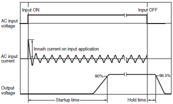
| Inrush current (for a cold start at 25°C) | For a cold start at 25°C. Refer to the following figure. | ||
| Output | Voltage adjustment range | If the output voltage adjuster (V. ADJ) is turned, the voltage will increase by more than +15% of the voltage adjustment range. When adjusting the output voltage, confirm the actual output voltage from the Power Supply and be sure that the load is not damaged. | |
| Ripple & Noise voltage | The value is when both rated output voltage and rated output current are satisfied. A characteristic when the ambient operating temperature is 25°C. | ||
| Input variation influence | This is the maximum variation in the output voltage when the input voltage is gradually changed within the allowable input voltage range at the rated output voltage and rated output current. | ||
| Load variation influence | This is the value when the output current is changed from 0 A to the rated output current while the input voltage is within the allowable input voltage. | ||
| Startup time | The value is when both rated output voltage and rated output current are satisfied. For a cold start at 25°C. Refer to the following figure. | ||
| Hold time | The value is when both rated output voltage and rated output current are satisfied. At 25°C. Refer to the following figure. | ||
| Additional functions | Overvoltage protection | Refer to Overvoltage Protection on Data Sheet for the time when input voltage shuts off and input turns on again. | |
| Reliability | Life expectancy | Refer to Recommended Replacement Periods and Periodic Replacement for Preventive Maintenance on Data Sheet for details. | |
| Standards | EMI | Conducted Emissions | The 150-W and higher models conform to Class B when an aluminum plate is set under the Power Supply. |
| Radiated Emissions | |||
Standard Compliance
• The input voltage range for compliance with EC Directives and other safety standards (UL, EN, etc.) is 90 to 264 VAC.
• EN/IEC 61558-2-16
To comply with EN/IEC 60204-1 (Machine Safety), a transformer is required in the control circuit. If, however, a Power Supply that has a built-in transformer that complies with EN/IEC 6155-8-2-16 is used, an external transformer is not required.
• Safety standard targets during a DC input *
During a DC input, UL 62368-1, cUR (CSA C22.2 No. 62368-1), EN/IEC 62368-1, EN 50178, EN/IEC 61558-2-16, and EN/IEC 60204-1 are safety standard targets. (The safety standards during a DC input are not acquired for the S8FS-G60048[].) It is possible to comply with the safety standards by connecting a UL-authenticated fuse. Select a UL-authenticated fuse that satisfies the following conditions:
S8FS-G015[][]/030[][] (320 VDC or above, 3 A)
S8FS-G050[][] (320 VDC or above, 4 A)
S8FS-G100[][] (320 VDC or above, 8 A)
S8FS-G150[][] (320 VDC or above, 10 A)
S8FS-G300[][] (320 VDC or above, 12 A)
S8FS-G600[][] (320 VDC or above, 20 A)
• To comply with the PELV output of the EN/IEC 60204-1, ground the output negative side (-V) to PE. *
* Applicable to products produced from May 2018
Inrush Current, Startup Time, Output Hold Time
Note:
The total inrush current of all of the Power Supplies will flow for parallel operation or backup operation.
Sufficiently check the fusing characteristics of fuses and the operating characteristics of breakers and select fuses and breakers so that external fuses will not burn out or breakers will not operate due to inrush current.
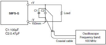
Ripple Noise Voltage
The specified standard for the ripple voltage noise was measured with a measurement circuit that is based on JEITA standard RC-9131A.
last update: May 14, 2018
- NO. S8FS-G
- TYPE:Power Supplies Switch mode power supplies
 Copyright Statement
 - DATE:2021-06-07
- Associated products:
S8VK-S S8VK-S (30/60/120/240/480-W Models)/Features S8FS-C Switch Mode Power Supply (15/25/35/50/75/100/150/200/350-W Models)/Features