
OMRON V680 SeriesAutomation Systems/ RFID Systems/HF Band RFID (13.56MHz)
OMRON V680 Series Automation Systems
OMRON V680 Series Dimensions
/Images/l_1863-25-119041-198x198.jpglast update: November 1, 2018
We enable the visualization of manufacturing sites.
The V680 series features electromagnetic induction and proprietary technologies to enable high-speed, high-reliability communication. This series of devices includes many useful startup and operational features, such as the visualization of communication status.
Even in global markets and manufacturing bases, these devices comply with the radio laws in all major countries to enable a consistent global deployment that provides traceability and production information management capability.
Our wide variety of RF tags, amplifiers, and controllers enables the visualization of all kinds of manufacturing sites, which helps increase productivity and improve quality.
Globally deployable

These devices are compliant with the ISO/IEC18000-3 international standard for RFID systems using the 13.56-MHz band that has become the global standard. These devices also comply with the radio laws of all major countries giving you peace of mind for deployments in global markets and manufacturing bases.
Custom system configurations

We offer a total solution with an extensive product lineup to support any application and objective including extremely small, 8-kbyte RF tags that do not need batteries, antennas, amplifiers, and controllers.
Visualization of communication

Visualization of the 7 communication modes provided on the front panels of amplifiers and controllers enables easy diagnosis without the need for host devices. In addition to making status confirmation easier for on-site operators, this also significantly reduces the time and labor required for installation, tuning, startup, and maintenance.
Globally deployable
Because these devices are compliant with ISO/IEC18000-3 (ISO/IEC15693) international standards, you can export these devices and easily integrate them with other equipment in local sites and facilities that are also compliant with ISO standards for overseas production.
Compliant with ISO/IEC18000-3 international standards
These devices are compliant with ISO/IEC18000-3 (ISO/IEC15693) international standards, offering peace of mind in relocating and exporting equipment to overseas locations.

Globally deployable in 51 countries around the world
Wireless device certification has been acquired in 51 countries, including Japan, European countries, and America, offering you peace of mind in utilizing these devices all around the world.
Contact us for more information on other supported countries. Visit the Omron website for the latest information on the radio device certification status of each country.

* Visit the Omron website for the latest information on the radio device certification status of each country.

Assembly line job instructions
Automated reading of vehicle model information, job instructions, and process history stored in RF tags prevents human errors and reduces costs related to defects and waste, even in mixed lines.

Traceability management
At each process, jobs are performed per the job instructions in RF tags followed by writing the results of the job into these RG tags. Central management of workers, manufacturing dates, and inspection data enables a reliable system of product traceability.

History and service life management
Installing RF tags to molds and antennas to molding machines enables mold information to be read from the RF tags. This enables easy management of cumulative shot time and shot counts, which impacts mold quality. If the wrong mold is accidentally mounted, automatic mold checks performed before the molding process can prevent production of defects.

Line sorting
Installing antennas at branch points enables you to easily construct sorting systems that read RF tag information on containers and use PLCs or other control systems to perform point sorting. The lack of mechanical structures, such as mechanical flags, enables the build-out of maintenance-free systems with very few failures.
Massive System Variation
We provide a wide variety of RFID components so that users can customize configurations for any installation space or objective, from replacing multiple sensor-based systems to managing large amounts of manufacturing data.
RF tags
This information medium is used to tie objects and information together. Our lineup includes devices of 1 kbyte to 8 kbytes. Select components based on storage amount and size of installation object.

Antennas
These devices are used to communicate with RF tags to read and write data. Select components based on communication distance and installation space.

Amplifiers & Controllers
Controls RFID operations including the sending of read data to host devices and writing instructions from host devices to RF tags.
Large capacity & High-speed


High-speed communication of up to 27 kbps via the 13.56-MHz band. Using the "Self-execution Mode" eliminates the need to access host devices, which significantly reduces takt time.

High-speed communication between Omron machine automation controllers and PLCs


Communication units enable direct connectivity between RFID systems and the NJ/NX series of Omron machine automation controllers and CS/CJ series of PLCs. Data reads/writes can be easily performed by simply setting parameters in the PLC memory area. Simple device configuration, in comparison with serial communication, is coupled with high-speed data processing. Communication programs can be easily built using the ladder program function blocks library (FB).

Supports DeviceNet™ Supports PROFIBUS
DeviceNet™ is a registered trademark of ODVA.


Manage manufacturing site information using open networks. Up to 58 bytes of data communication can be enabled simply by changing DIP switch settings.

Optimal for use in device identification


Includes functionality equivalent to 16 detection sensors. This means that approximately 64,000 identifications using 16-bit RF tag communication can be performed. This can be used in line sorting operations, device identification, and process progress management.

We also provide handheld reader/writers.

Visualization of communication
Amplifiers and controllers are equipped with display functionality for startup, tuning, and easy diagnostics operations.
This functionality increases on-site startup and maintenance efficiency.
Easily perform RFID system diagnosis
Stability of communication can be confirmed via amplifiers and controllers directly without the need to use a PC or other host device.
Visualization 1 Communication Stability
Visualization of communication stability
The stability of communication between antennas and RF tags can be checked by anyone, anytime, with time and cost reduction.

6-level indication of distance between antennas and RF tags

Distance in relation to the range of communication between antennas and RF tags is indicated in 6 levels. Installation positions of antennas and RG tags can be easily set and checked.

Speed level measuring mode

This mode enables the confirmation of RF tag movement speed and the number of available bytes. Devices repeatedly communicate with moving RF tags to display the communication success rate and speed level between a range of levels from 01 to 99.

Communication success rate measuring mode

This mode is used to check the communication success rate between antennas and RF tags. The communication process is executed 100 times without any retries to display a communication success rate between levels of 01 to 99.

Visualization 2 Noise Status
Visualization of noise status
This feature is used to check if there is any noise in the area that could cause communication issues. This feature is useful for pre-checks and for reducing downtime when communication errors occur. This feature also gives you peace of mind in deploying RFID systems in environments near sources of drive power, which are prone to noise, and other environments with poor radio signal reception.

Noise level measuring mode

This feature measures the noise level in the space between RF tag and antenna installations and displays the noise level between a range of 00 to 99. The ambient noise level, source of noise, and effect of noise reduction efforts all appear as level indicators for ease of use and peace of mind

LEDs indicate noise levels

A combination of LEDs is used to indicate ambient noise status.

Visualization 3 Error Causes
Visualization of error causes
This feature enables you to see when line errors occur and their causes. This feature is useful for reducing downtime when issues occur.

Confirmation of line errors

LEDs in amplifiers indicate error information when errors occur. This feature enables you to quickly confirm line errors, which helps to reduce downtime when issues occur.

Type of error indicated by LEDs

Combinations of red flashing LEDs are used to indicate RF tag communication errors, RF tag missing errors, and other error causes.

Efficient Management of RF Tag Memory Maps

What information is written to and read from RF tags at what process? The amount of data required for operations is enormous and changes frequently. Manual verification and management takes significant time and is also prone to human error. ID Map Manager is a memory map creation, management, and testing tool designed to eliminate these issues and help make operations more efficient. Centralized management of RF tag data helps reduce time required for memory allocation, design, and verification processes.

last update: November 1, 2018
Purchase the OMRON HF Band RFID (13.56MHz) Please fill in the following
If you have just landed here, this product OMRON V680 Series Automation Systems,Automation Systems is offered online by Tianin FLD Technical Co.,Ltd. This is an online store providing Automation Systems at wholesale prices for consumers. You can call us or send enquiry, we would give you the prices, packing,deliverty and more detailed information on the V680 Series We cooperate with DHL,TNT,FEDEX,UPS,EMS,etc.They guarantee to meet your needs in terms of time and money,even if you need your OMRON V680 SeriesAutomation Systems tomorrow morning (aka overnight or next day air) on your desk, 2, 3 days or more.Note to international customers, YES, we ship worldwide.
NY5[][]-1 Industrial PC Platform NY-series IPC Machine Controller/Features
E63-WF Direct Discrimination Unit/Features
G9SA Safety Relay Unit/Features
SRT2-VID / VOD(-1) Transistor Remote I/O Terminals with Connectors (8/16 Points)/Features
XS2 Round Water-resistant Connectors (M12 Threads)/Features
OMRON V680 Series dimension
V680 Series RFID System/Dimensionslast update: November 1, 2018
(Unit: mm)
Tolerance class IT16 applies to dimensions in this datasheet unless otherwise specified.
RF Tag
V680-D1KP52MT/-D2KF52M
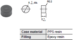
V680-D1KP53M
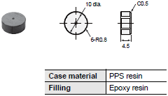
V680-D1KP54T
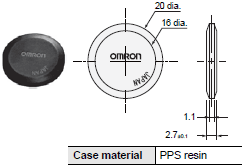
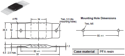
V680-D1KP66T/-D1KP66MT
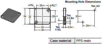
V680-D1KP66T-SP
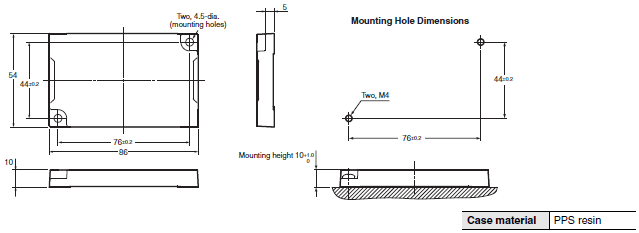
V680S-D2KF67/-D2KF67M
V680S-D8KF67/-D8KF67M

V680S-D2KF68/-D2KF68M
V680S-D8KF68/-D8KF68M
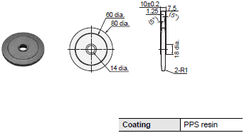
V680-D1KP58HTN
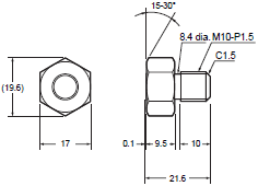
V680-D1KP52M-BT01
V680-D2KF52M-BT01
V680-D1KP52M-BT11
V680-D2KF52M-BT11
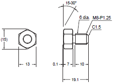
Antenna with Detachable Amplifier Unit
V680-HS52-W

V680-HS52-R

V680-HS51

V680-HS63-W

V680-HS63-R

V680-HS65-W

V680-HS65-R

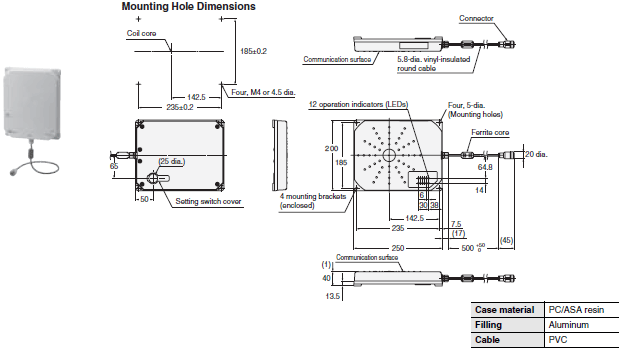
Antenna with Built-in Amplifier Unit
V680-H01-V2
Amplifier Unit
V680-HA63A/-HA63B

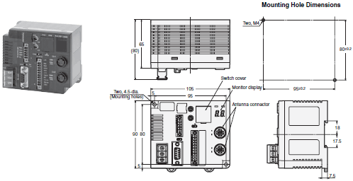
ID Controller
V680-CA5D01-V2/-CA5D02-V2
RFID Units
NX-V680C1 (One-channel)
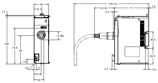
NX-V680C2 (Two-channels)
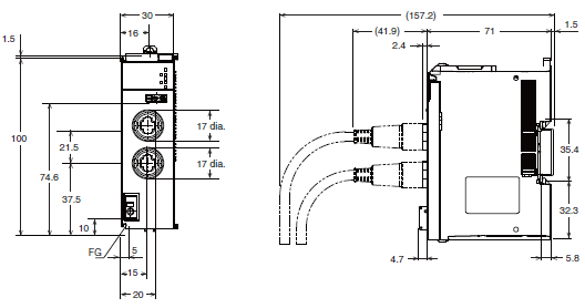
ID Sensor Units
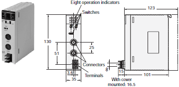
CJ1W-V680C11
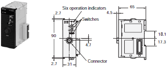
CJ1W-V680C12
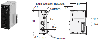
CS1W-V680C11
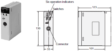
CS1W-V680C12
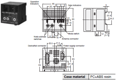
Amplifier-integrated Controller (DeviceNet ID Slave/PROFIBUS ID Slave)
V680-HAM42-DRT
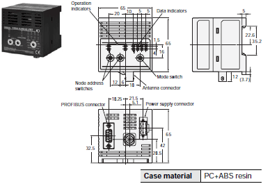
V680-HAM42-PRT
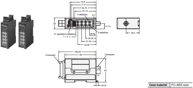
Amplifier-integrated Controllers (ID Flag Sensors)
V680-HAM91/-HAM81
Handheld Reader Writer
V680-CHUD

V680-CH1D

V680-CH1D-PSI

Interface Cables (Sold Separately)
V680-A60 2M/5M/10M

Note: The connectors are not waterproof.
AC Adapter
V600-A22

Accessories
V680-D1KP66T Attachments
V600-A86

V680-D8KF68/-D32KF68 Attachments
V680-A81

V680-D1KP58HTN Attachments
V680-A80

V680-D1KP54T Attachments
V700-A80

Amplifier Unit Special Extension Cable
V700-A40 2M
V700-A41 3M
V700-A42 5M
V700-A43 10M
V700-A44 20M
V700-A45 30M

V680-H01 Special Cables
V700-A40-W 2M
V700-A40-W 5M
V700-A40-W 10M
V700-A40-W 20M
V700-A40-W 30M

last update: November 1, 2018
OMRON V680 Series catalog
V680 Series RFID System/Catalog- Catalog
- Manual
- CAD
English
Global Edition
| Catalog Name | Catalog Number [size] | Last Update | |
|---|---|---|---|
| | Q267-E1-01 [17056KB] | Nov 01, 201820181101 | V680 Series Data Sheet |
| | Q266-E1-01 [83175KB] | Nov 01, 201820181101 | V680 Series Catalog |
OMRON V680 Series specification
V680 Series RFID System/Specificationslast update: November 1, 2018
RF Tag (1-kbyte Memory)
| Model | V680- D1KP52MT | V680- D1KP54T | V680- D1KP66T | V680- D1KP66MT | V680- D1KP53M | V680- D1KP66T-SP |
|---|---|---|---|---|---|---|
| Memory capacity | 1,000 byte (user area) | |||||
| Memory type | EEPROM | |||||
| Data retention time *1 | 10 years after writing (85 °C max.) | |||||
| Write endurance | 100,000 times per block (at 25 °C) | |||||
| Ambient operating temperature (during communication) | - 25 to 85 °C (with no icing) | - 25 to 70 °C (with no icing) | ||||
| Ambient storage temperature (during data backup) | -40 to 125°C (with no icing) Heat resistance: 1,000 thermal cycles each of 30 minutes at -10°C/150°C, Hightemperature storage: 1,000 hours at 150°C *2 200 thermal cycles each of 30 minutes at -10°C/180°C, Hightemperature storage: 200 hours at 180°C *3 | -40 to 125°C (with no icing) | - 40 to 110 °C (with no icing) | |||
| Ambient operating humidity | 35 to 95% | |||||
| Degree of protection | IP68 (IEC 60529:2001) Oil resistance equivalent to IP67G (JIS C 0920:2003, Appendix 1) *4 | IP67 (IEC 60529:2001) Oil resistance equivalent to IP67G (JIS C 0920:2003, Appendix 1) *4 | IP68 (IEC 60529:2001) Oil resistance equivalent to IP67G (JIS C 0920:2003, Appendix 1) *4 | IP67 | ||
| Vibration resistance | 10 to 2,000 Hz, 1.5-mm double amplitude at 150 m/s2 acceleration with 10 sweeps in X, Y, and Z directions for 15 minutes each | |||||
| Shock resistance | 500 m/s2 in X, Y, and Z directions 3 times each (18 times in total) | |||||
| Appearance | 8 dia. × 5 mm | 20 dia. × 2.7 mm | 34 × 34 × 3.5 mm | 10 dia. × 4.5 mm (DIN698373) | 95 × 36.5 × 6.5 mm (excluding protrusions) | |
| Materials | Case: PPS resin Filling: Epoxy resin | Molding: PPS resin | Case: PPS resin Filling: Epoxy resin | External resin: PFA Tag body: PPS resin | ||
| Weight | Approx. 0.5 g | Approx. 2 g | Approx. 6 g | Approx. 7.5 g | Approx. 1 g | Approx. 20 g |
| Metallic compatibility | Yes | No | No | Yes | Yes | No |
Note: For details, refer to the User's Manual (Cat. No. Z262).
*1. Refer to the User's Manual (Cat. No. Z262) for data retention time for temperatures of 85°C or higher. If the V680 has
been stored at 125°C or higher, write the data again even if the data does not need to be changed.
*2. 150°C heat resistance: The heat resistance has been checked at 150°C for up to 1,000 hours, and thermal shock has
been checked through testing 1,000 thermal cycles each of 30 minutes at −10/150°C. (Test samples: 22, defects: 0)
*3. 180°C heat resistance: The heat resistance has been checked at 180°C for up to 200 hours, and thermal shock has
been checked through testing 200 thermal cycles each of 30 minutes at −10°C/180°C. (Test samples: 22, defects: 0)
*4. Oil resistance has been tested using a specific oil as defined in the OMRON test method.
RF Tag with 1-kbyte Memory with High-temperature Capability
| Model | V680-D1KP58HTN |
|---|---|
| Memory capacity | 1,000 bytes (user area) |
| Memory type | EEPROM |
| Data Retention | 10 years after writing (85°C or less), 0.5 year after writing (85°C to 125°C) Total data retention at high temperatures exceeding 125°C is 10 hours *1 |
| Write Endurance | 100,000 times per block (25°C) |
| Ambient operating temperature | -25°C to 85°C (with no icing) |
| Ambient storage temperature | -40 to 250°C (with no icing) *2 (Data retention: -40 to 125°C) 1. 2,000 cycles of 30 minutes each between room temperature and 200°C 2. 500 hours at 250°C |
| Ambient storage humidity | No restrictions. |
| Degree of protection | IP67 (IEC 60529:2001) Oil resistance equivalent to IP67G (JIS C 0920:2003, Appendix 1) *3 |
| Vibration resistance | 10 to 2,000 Hz, 1.5-mm double amplitude, acceleration: 150 m/s2, 10 sweeps each in X, Y, and Z directions for 15 minutes each |
| Shock resistance | 500 m/s2, 3 times each in X, Y, and Z directions (total: 18 times) |
| Materials | PPS resin |
| Weight | Approx. 70 g |
*1 After storing data at high temperatures, rewrite the data even if changes are not required. High temperatures are
those exceeding 125°C up to 250°C.
*2 Storing RF Tags under high temperatures or under heat cycles will adversely affect the performance of the
internal parts and the service life of the RF Tags.
The RF Tag were placed in the following high temperatures and then evaluated in-house.
It was confirmed that no problems occurred.
1. 2,000 cycles of 30 minutes each between room temperature and 200°C.
2. 500 hours at 250°C.
*3 Oil resistance has been tested using a specific oil as defined in the OMRON test method.
RF Tag (2-kbyte Memory)
| Model | V680S- D2KF67 | V680S- D2KF67M | V680S- D2KF68 | V680S- D2KF68M | V680-D2KF52M |
|---|---|---|---|---|---|
| Memory capacity | 2,000 bytes (user area) | ||||
| Memory type | FRAM | ||||
| Data retention time *1 | 10 years after writing at 85°C | 10 years after writing (55°C max.) | |||
| Write endurance | One trillion writes for each block(85°C or less), Number of accesses *2: One trillion writes | Access frequency per block *2: 10 billion times | |||
| Ambient operating temperature | -20 to 85°C (with no icing) | -25 to 85°C (with no icing) | |||
| Ambient storage temperature | -40 to 125°C (with no icing) | -40 to 125°C (with no icing) | |||
| Ambient operating humidity | 35 to 85% | 35 to 95% | |||
| Degree of protection | IP68 (IEC 60529:2001), Oil resistance equivalent to IP67G (JIS C 0920:2003, Appendix 1) *3 IPX9K (DIN 40 050) | IP67 (IEC 60529:2001) Oil resistance equivalent to IP67G (JIS C 0920:2003, Appendix 1) *3 | |||
| Vibration resistance | 10 to 2,000 Hz, 1.5-mm double amplitude at 150 m/s2 acceleration with 10 sweeps in X, Y, and Z directions for 15 minutes each | No abnormality after application of 10 to 500 Hz, 1.5-mm double amplitude, acceleration: 100 m/s2, 10 sweeps each in X, Y, and Z directions for 11 minutes each | 10 to 2,000 Hz, 1.5-mm double amplitude at 150 m/s2 acceleration with 10 sweeps in X, Y, and Z directions for 15 minutes each | ||
| Shock resistance | 500 m/s2 in X, Y, and Z directions 3 times each (Total:18 times) | ||||
| Appearance | 40 × 40 × 5 mm | 86 × 54 × 10 mm | 8 dia. × 5 mm | ||
| Materials | Exterior: PPS resin | Case: PPS resin Filling: Epoxy resin | |||
| Weight | Approx. 12 g | Approx. 11.5 g | Approx. 44 g | Approx. 46 g | Approx. 0.5 g |
| Metallic compatibility | No | Yes | No | Yes | Yes |
Note: For details, refer to the User’s Manual (Cat. No. Z248 or Z339).
*1. Refer to the User's Manual (Cat. No. Z248) for data retention time for temperatures of 55°C or higher.
*2. The total Read or Write communication frequency is called the access frequency.
*3. Oil resistance has been tested using a specific oil as defined in the OMRON test method.
RF Tag with 8-kbyte Memory
| Model | V680S-D8KF67 | V680S-D8KF67M | V680S-D8KF68 | V680S-D32KF68M |
|---|---|---|---|---|
| Memory capacity | 8,192 bytes (user area) | |||
| Memory type | FRAM | |||
| Data retention time | 10 years after writing (85°C or less) | |||
| Write endurance | 1 trillion times per block. *1 Access frequency: 1 trillion times: | |||
| Ambient operating temperature | -20 to 85°C (with no icing) | |||
| Ambient storage temperature | -40 to 125°C (with no icing) | |||
| Ambient operating humidity | 35 to 85% | |||
| Degree of protection | IP68 (IEC 60529:2001), Oil resistance equivalent to IP67G (JIS C 0920:2003, Appendix 1) *2 IPX9K (DIN 40 050) | |||
| Vibration resistance | 10 to 2,000 Hz, 1.5-mm double amplitude at 150 m/s2 acceleration with 10 sweeps in X, Y, and Z directions for 15 minutes each | 10 to 500 Hz, 1.5-mm double amplitude at 100 m/s2 acceleration with 10 sweeps in X, Y, and Z directions for 11 minutes each | ||
| Shock resistance | 500 m/s2 in X, Y, and Z directions 3 times each (18 times in total) | |||
| Dimensions | 40 × 40 × 4.5 mm | 86 × 54 × 10 mm | ||
| Materials | Molding: PPS resin | |||
| Weight | Approx. 11.5 g | Approx. 12 g | Approx. 44 g | Approx. 46 g |
| Metallic compatibility | No | Yes | No | Yes |
Note: For details, refer to the User’s Manual (Cat. No. Z339).
*1. The total Read or Write communication frequency is called the access frequency.
*2. Oil resistance has been tested using a specific oil as defined in the OMRON test method.
Bolt RF Tags (1-kbyte Memory)
| Model | V680-D1KP52M-BT01 | V680-D1KP52M-BT11 |
|---|---|---|
| Memory capacity | 1,000 bytes (user area) | |
| Memory type | EEPROM | |
| Data retention time | 10 years after writing (85°C or less), 0.5 years after writing (85 to 125°C) Total data retention at high temperatures exceeding 125°C is 10 houres | |
| Write endurance | 100,000 times per block (at 25°C) | |
| Ambient operating temperature (during communication) | -25 to 85°C (with no icing) | |
| Ambient storage temperature (during data backup) | -40 to 125°C (with no icing) | |
| Ambient operating humidity | 35 to 95% | |
| Degree of protection | IP68 (IEC 60529:2001) Oil resistance equivalent to IP67G (JIS C 0920:2003, Appendix 1) * | |
| Vibration resistance | 10 to 2,000 Hz, 1.5-mm double amplitude at 150 m/s2 acceleration with 10 sweeps in X, Y, and Z directions for 15 minutes each | |
| Shock resistance | 500 m/s2 in X, Y, and Z directions 3 times each (18 times in total) | |
| Materials | Bolt: SUS303, Case (RF Tag): PPS resin, Filling (RF Tag): Epoxy resin | |
| Weight | Approx. 25 g | Approx. 10 g |
* Oil resistance has been tested using a specific oil as defined in the OMRON test method.
Bolt RF Tags (2-kbyte Memory)
| Model | V680-D2KF52M-BT01 | V680-D2KF52M-BT11 |
|---|---|---|
| Memory capacity | 2,000 bytes (user area) | |
| Memory type | FRAM | |
| Data retention time | 10 years after writing (55°C or less), 2.9 years after writing (85°C max.) | |
| Write endurance | 10 billion reads/writes per block, Number of accesses *1: 10 billion times | |
| Ambient operating temperature (during communication) | -25°C to 85°C (with no icing) | |
| Ambient storage temperature (during data backup) | -40°C to 85°C (with no icing) | |
| Ambient operating humidity | 35 to 95% | |
| Degree of protection | IP67 (IEC 60529:2001) Oil resistance equivalent to IP67G (JIS C 0920:2003, Appendix 1) *2 | |
| Vibration resistance | 10 to 2,000 Hz, 1.5-mm double amplitude at 150 m/s2 acceleration with 10 sweeps in X, Y, and Z directions for 15 minutes each | |
| Shock resistance | 500 m/s2 in X, Y, and Z directions 3 times each (18 times in total) | |
| Materials | Bolt: SUS303, Case (RF Tag): PPS resin, Filling (RF Tag): Epoxy resin | |
| Weight | Approx. 25 g | Approx. 10 g |
*1 The number of accesses is the total number of communications for reading or writing.
*2 Oil resistance has been tested using a specific oil as defined in the OMRON test method.
Cylindrical Antenna (Detachable Amplifier Unit Type)
| Model | V680-HS51 (Standard Cable, Non-waterproof Connector) | V680-HS52-W (Standard Cable, Waterproof Connector) | V680-HS52-R (Standard Cable, Non-waterproof Connector) |
|---|---|---|---|
| Ambient operating temperature | -10°C to 60°C (with no icing) | ||
| Ambient storage temperature | -25°C to 75°C (with no icing) | ||
| Ambient operating humidity | 35% to 95% (with no condensation) | ||
| Insulation resistance | 20 MΩ min. (at 500 VDC) between the cable terminals and the case | ||
| Dielectric strength | 1,000 VAC (50/60 Hz) for 1 minute between the cable terminals and the case with a current leakage of 5 mA max. | ||
| Degree of protection | IP67 (IEC 60529:2001) Oil resistance equivalent to IP67G (JIS C 0920:2003, Appendix 1) (Antenna portion) *2 | IP67 (IEC 60529:2001) Oil resistance equivalent to IP67G (JIS C 0920:2003, Appendix 1) (Antenna portion) *1 | IP67 (IEC 60529:2001) Oil resistance equivalent to IP67G (JIS C 0920:2003, Appendix 1) (Antenna portion) *2 |
| Vibration resistance | 10 to 2,000 Hz variable vibration, 1.5-mm double amplitude at 150 m/s2 acceleration, with 10 sweeps in X, Y, and Z directions for 15 minutes each | 10 to 500 Hz variable vibration, 1.5-mm double amplitude at 100 m/s2 acceleration, with 10 sweeps in X, Y, and Z directions for 8 minutes each | |
| Shock resistance | 1,000 m/s2 in X, Y, and Z directions 3 times each (18 times in total) | 500 m/s2 in X, Y, and Z directions 3 times each (18 times in total) | |
| Appearance | M12 × 35 mm | M22 × 65 mm | |
| Materials | ABS, brass, epoxy resin filling | ||
| Weight | Approx. 55 g (with 2-m cable) | Approx. 850 g (with 12.5-m cable) | |
Note: For details, refer to the User’s Manual (Cat. No. Z248 or Z262).
*1. The degree of protection for the Connector is IP67/IP65. This OMRON in-house standard confirms resistance to
cutting and other oils. It is equivalent to the former JEM1030 standard.
*2. The Connector is not waterproof. Oil resistance has been tested using a specific oil as defined in the OMRON test
method.
Square Antenna (Detachable Amplifier Unit Type)
| Model | V680-HS63-W (Standard Cable, Waterproof Connector) | V680-HS63-R (Flexible Cable, Non-waterproof Connector) |
|---|---|---|
| Ambient operating temperature | -10°C to 60°C (with no icing) | |
| Ambient storage temperature | -25°C to 75°C (with no icing) | |
| Ambient operating humidity | 35% to 95% (with no condensation) | |
| Insulation resistance | 20 MΩ min. (at 500 VDC) between the cable terminals and the case | |
| Dielectric strength | 1,000 VAC (50/60 Hz) for 1 minute between the cable terminals and the case with a current leakage of 5 mA max. | |
| Degree of protection | IP67 (IEC 60529:2001) Oil resistance equivalent to IP67G (JIS C 0920:2003, Appendix 1) (Antenna portion) *1 | IP67 (IEC 60529:2001) Oil resistance equivalent to IP67G (JIS C 0920:2003, Appendix 1) (Antenna portion) *2 |
| Vibration resistance | 10 to 500 Hz variable vibration, 1.5-mm double amplitude at 100 m/s2 acceleration, with 10 sweeps in X, Y, and Z directions for 11 minutes each | |
| Shock resistance | 500 m/s2 in X, Y, and Z directions 3 times each (18 times in total) | |
| Appearance | 40 × 53 × 23 mm | |
| Materials | ABS, epoxy resin filling | |
| Weight | Approx. 850 g (with 12.5-m cable) | |
| Model | V680-HS65-W (Standard Cable, Waterproof Connector) | V680-HS65-R (Flexible Cable, Non-waterproof Connector) |
|---|---|---|
| Ambient operating temperature | -25°C to 70°C (with no icing) | |
| Ambient storage temperature | -40°C to 85°C (with no icing) | |
| Ambient operating humidity | 35% to 95% (with no condensation) | |
| Insulation resistance | 20 MΩ min. (at 500 VDC) between the cable terminals and the case | |
| Dielectric strength | 1,000 VAC (50/60 Hz) for 1 minute between the cable terminals and the case with a current leakage of 5 mA max. | |
| Degree of protection | IP67 (IEC 60529:2001) Oil resistance equivalent to IP67G (JIS C 0920:2003, Appendix 1) (Antenna portion) *1 | IP67 (IEC 60529:2001) Oil resistance equivalent to IP67G (JIS C 0920:2003, Appendix 1) (Antenna portion) *2 |
| Vibration resistance | 10 to 500 Hz variable vibration, 1.5-mm double amplitude at 100 m/s2 acceleration, with 10 sweeps in X, Y, and Z directions for 11 minutes each | |
| Shock resistance | 500 m/s2 in X, Y, and Z directions 3 times each (18 times in total) | |
| Appearance | 100 × 100 × 30 mm | |
| Materials | ABS, epoxy resin filling | |
| Weight | Approx. 1,100 g (with 12.5-m cable) | |
Note: For details, refer to the User’s Manual (Cat. No. Z248 or Z262).
*1. The degree of protection for the Connector is IP67/IP65. Oil resistance has been tested using a specific oil as defined
in the OMRON test method.
*2. The Connector is not waterproof. Oil resistance has been tested using a specific oil as defined in the OMRON test
method.
Square Antenna with Built-in Amplifier
| Model | V680-H01-V2 |
|---|---|
| Ambient operating temperature | -10°C to 55°C (with no icing) |
| Ambient storage temperature | -35°C to 65°C (with no icing) |
| Ambient operating humidity | 35% to 85% (with no condensation) |
| Insulation resistance | 20 MΩ min. (at 100 VDC) between connector terminals and the rear plate |
| Dielectric strength | 1,000 VAC, 50/60 Hz for 1 min between connector terminals and the rear plate |
| Degree of protection | IP63.(IEC60529); Mounting direction: Communications surface facing up |
| Vibration resistance | 10 to 150 Hz, 0.35-mm single amplitude, acceleration: 50 m/s2, 10 sweeps in each of 3 axis directions (up/down, left/right, and forward/backward) for 8 minutes each |
| Shock resistance | 150 m/s2, 3 times each in 6 directions (Total: 18 times) |
| Appearance | 200 × 250 × 40 mm |
| Material | Polycarbonate (PC) resin, ASA resin/Rear Panel: Aluminum |
| Weight | Approx. 900 g |
| Cable length | 0.5 m (use a relay cable to connect to the Controller up to 30.5 m) |
Note: For details, refer to the User’s Manual (Cat. No. Z248 or Z262).
Amplifier Unit
| Model | V680-HA63A | V680-HA63B |
|---|---|---|
| Ambient operating temperature | -10°C to 55°C (with no icing) | |
| Ambient storage temperature | -25°C to 65°C (with no icing) | |
| Ambient operating humidity | 35% to 85% (with no condensation) | |
| Insulation resistance | 20 MΩ min. (at 500 VDC) between the cable terminals and the case | |
| Dielectric strength | 1,000 VAC (50/60 Hz) for 1 minute between the cable terminals and the case with a current leakage of 5 mA max. | |
| Degree of protection | IP40 (IEC60529) *1 | IP67/IP65 (IEC60529) *2 |
| Vibration resistance | 10 to 500 Hz variable vibration, 1.5-mm double amplitude at 100 m/s2 acceleration, with 10 sweeps in X, Y, and Z directions for 11 minutes each | |
| Shock resistance | 500 m/s2 in X, Y, and Z directions 3 times each (18 times in total) | |
| Appearance | 25 × 40 × 65mm (not including projections) | |
| Material | Polycarbonate (PC) resin | |
| Weight | Approx. 650 g (with 10-m cable) | |
| Cable length | 5 m, 10 m | |
| Transmittable RF Tags | 1-kbyte memory | 2-, 8-kbyte memory |
Note: For details, refer to the User’s Manual (Cat. No. Z248 or Z262).
*1. When connected to the V680-HS[][]-R or V680-HS52-R.
*2. When connected to the V680-HS[][]-W or V680-HS52-W. (Not including the Connector on the Controller.)
ID Controller
| Model | V680-CA5D01-V2 | V680-CA5D02-V2 |
|---|---|---|
| Power supply voltage (Power consumption) | 24 VDC (-15% to +10%) 15 W max., 0.8 A max. | |
| Communications Specifications | RS-232C, RS-422, RS-485 | |
| Input Specifications (Input voltage) RST, TRG1, and TRG2 | 24 VDC (+10% to -15%, including ripple) (PNP and NPN compatible) | |
| Output Specifications (Maximum switching capacity) RUN, BUSY/OUTS, ERROR/OUT4, OUT1, and OUT2 | 24 VDC (+10% to -15%, including ripple) PNP and NPN compatible | |
| Ambient operating temperature | -10 to 55°C (with no icing) | |
| Ambient storage temperature | -25 to 65°C (with no icing) | |
| Ambient operating humidity | 25% to 85% (with no condensation) | |
| Insulation resistance | 20 MΩ min. (at 500 VDC) applied as follows: (1) Between power supply terminals and grounded case (2) Between ground and terminals | |
| Dielectric strength | 1,000 VAC (50/60 Hz) for 1 minute (1) Between power supply terminals and grounded case (2) Between ground and terminals | |
| Degree of protection | Panel mounted (equivalent to IP20) | |
| Vibration resistance | 10 to 150 Hz variable vibration, 0.2-mm double amplitude at 15 m/s2 acceleration, with 10 sweeps in X, Y, and Z directions for 8 minutes each | |
| Shock resistance | 150 m/s2 | |
| Appearance | 105 × 90 × 65 mm (not including projections) | |
| Material | Polycarbonate (PC) resin, ABS resin | |
| Weight | Approx. 300 g | |
| Connectable Amplifier Units | 1 | 2 |
Note: For details, refer to the User's Manual (Cat. No. Z249).
USB Port
The USB port is used for a simple connection with a personal computer using a USB cable. The port complies with USB 1.1, and the USB cable uses a series A or series mini-B connector. A USB port driver must be separately provided. Consult with your OMRON representative for details.
When connected to a host device via USB, the communications will use 1:1 protocol regardless of the setting of DIP switches 3 to 9.
The USB port is not used for control purposes. When building a system, be sure to provide an RS-232C port or RS-422/RS-485C port.
RFID Units
| Model | NX-V680C1 | NX-V680C2 | |
|---|---|---|---|
| Enclosure | Mounted in a panel | ||
| Grounding Methods | Ground to less than 100 Ω | ||
| Operating environm ent | Ambient operating temperature | 0 to 55°C | |
| Ambient operating humidity | 10 to 95% (with no condensation or icing) | ||
| Atmosphere | Must be free from corrosive gases. | ||
| Ambient storage temperature | -25 to 70°C (with no condensation or icing) | ||
| Altitude | 2,000 m max. | ||
| Pollution degree | 2 or less: Conforms to JIS B3502 and IEC 61131-2 | ||
| Noise immunity | 2 kV on power supply line (Conforms to IEC61000-4-4.) | ||
| Overvoltage category | Category II: Conforms to JIS B3502 and IEC 61131-2 | ||
| EMC immunity level | Zone B | ||
| Vibration resistance | Conforms to IEC 60068-2-6. 5 to 8.4 Hz with amplitude of 3.5 mm, 8.4 to 150 Hz, acceleration of 9.8 m/s2 100 min each in X, Y, and Z directions (10 sweeps of 10 min each = 100 min total) | ||
| Shock resistance | Conforms to IEC 60068-2-27, 147 m/s2, 3 times each in X, Y, and Z directions | ||
| Applicable standards | cULus: Listed (UL61010-2-201), ANSI/ISA12.12.01, EU: EN61131-2, RCM, KC: KC Registration, EAC | ||
| No. of Amplifier/Antenna connections | 1 | 2 | |
RFID Units Functions
| Function name | NX-V680C1/NX-V680C2 |
|---|---|
| RF Communications option function | This function switches the operation sequence during communications with an RF Tag. |
| Communications command function | This function reads or writes the memory for a RF Tag on the antenna communications area. |
| Write protection function | This function prevents the loss of data due to overwriting by specifying the areas in which it is not possible to write to an RF Tag. |
| RF Tag service life detection function | This function records the number of times data is rewritten to an RF Tag, and determines the maximum rewrite count. |
| RF Tag memory error detection function | This function detects an error during reading by performing CRC calculation for the memory of an RF Tag. |
| RF Tag memory error correction function | This function detects an error during reading by performing ECC calculation for the memory of an RF Tag, and corrects the error to an appropriate value |
| Test command function | This function checks the margin in communications with an RF Tag, and measures the surrounding noise. |
ID Sensor Units
| Model | CJ1W-V680C11 | CJ1W-V680C12 | CS1W-V680C11 | CS1W-V680C12 | |
|---|---|---|---|---|---|
| Current consumption | Internal: 5 V | 260 mA | 320 mA | 260 mA | 320 mA |
| Internal: 24 V/26 V | 130 mA * | 260 mA | 125 mA * | - | |
| External: 24 V | - | - | - | 360 mA | |
| Ambient operating temperature | 0 to 55°C | ||||
| Ambient storage temperature | -20°C to 75°C | ||||
| Ambient operating humidity | 10% to 90% (with no condensation) | ||||
| Insulation resistance | 20 mΩ min. at 500 VDC | ||||
| Dielectric strength | 1,000 VAC for 1 minute | ||||
| Degree of protection | Mounted in panel (IP30) | ||||
| Vibration resistance | 10 to 57 Hz variable vibration, 0.075-mm double amplitude and 57 to 150 Hz variable vibration at 9.8 m/s2 acceleration, with 10 sweeps in X, Y, and Z directions for 8 minutes each | ||||
| Shock resistance | 147 m/s2 in X, Y, and Z directions 3 times each | ||||
| Appearance | 31 × 65 × 90 mm (excluding protrusions) | 35 × 130 × 101 mm (excluding protrusions) | |||
* When connected to the V680-H01: 280 mA. The V680-H01-V2 can be connected only to a 1-channel ID Sensor Unit.
A 2-channel Unit cannot be used.
Functional Specifications of ID Sensor Units
| Model | CJ1W-V680C11 | CJ1W-V680C12 | CS1W-V680C11 | CS1W-V680C12 |
|---|---|---|---|---|
| Communications control protocol | Special protocol for CS, CJ and NJ PLCs | |||
| Number of Antenna connections | 1 | 2 | 1 | 2 |
| Commands | Supported commands: Read, Write, Bit Set/Bit Clear, Mask Bit Write, Calculation Write, Data Fill, Data Check, Number of Writes Control, Copy (CJ1W-V680C12 and CS1W-V680C12 only), Read with Error Correction/Write with Error Correction, UID Read, and Noise Measurement. The following communications options are supported: Single trigger, Single auto, Repeat auto, FIFO trigger, FIFO repeat *, Multi-access trigger, and Multi-access repeat * | |||
| Data transfer quantity | 2,048 bytes max. (160 bytes/scan) | |||
| Diagnostic function | (1) CPU watchdog timer (2) Communications error detection with RF Tag (3) Antenna power supply error | |||
| Monitoring/testing functions | Tag communications can be tested in Test Mode. Status is displayed by LED indicators. | |||
| Number of allocated words | 10 words | 20 words | 10 words | 20 words |
Note: For details, refer to the User's Manual (Cat. No. Z271).
* Cannot be used for communications with the V680-D1KP[][].
Amplifier-integrated Controller (DeviceNet ID Slave/PROFIBUS ID Slave)
| Model | V680-HAM42-DRT | V680-HAM42-PRT |
|---|---|---|
| Network compatibility | DeviceNet | PROFIBUS DP-V0 |
| Connectable Antennas | One channel (V680-HS[][]) | |
| Rated voltage | 24 VDC (-15% to 10%) including 10% ripple (p-p) | |
| Power consumption | 4 W max. (Current consumption of 200 mA max. at power supply voltage of 24 VDC) | |
| Ambient operating temperature | -10 to 55°C (with no icing) | |
| Ambient storage temperature | -25 to 65°C (with no icing) | |
| Ambient operating humidity | 25% to 85% (with no condensation; ambient operating temperature is 40°C max. at humidity of 85%) | |
| Insulation resistance | 20 MΩ min. (at 500 VDC) between all terminals excluding the ground terminal and the case | |
| Dielectric strength | 1,000 VAC (50/60 Hz) for 1 minute between all terminals excluding the ground terminal and the case | |
| Vibration resistance | 10 to 150 Hz, 0.2-mm double amplitude at 15 m/s2 acceleration with 10 sweeps in X, Y and Z directions for 8 minutes each | |
| Shock resistance | 150 m/s2 in X, Y, and Z directions 3 times each (18 times in total) | |
| Appearance | 65 × 65 × 65 mm (excluding protrusions) | |
| Degree of protection | IEC 60529, IP20 | |
| Materials | Polycarbonate (PC) resin, ABS resin | |
| Weight | Approx. 150 g | |
| Mounting | DIN Track | |
Note: 1. For details, refer to the User's Manual (Cat. No. Z278).
2. The number of words allocated in the master depends on the Access Mode.
Amplifier-integrated Controllers (ID Flag Sensors)
| Model | V680-HAM91 | V680-HAM81 |
|---|---|---|
| Rated voltage | 24 VDC (-15% to +10%) including 10% ripple (p-p) | |
| Power consumption | 3.5 W (24 VDC, 150 mA max. except external I/O line current) | |
| Input specifications | Transistor output Short-circuit current: 3 mA (typical) (for short-circuit between IN terminal and 0 V), OFF voltage: 15 to 30 VDC, ON voltage: 0 to 5 VDC, Input impedance: 8.2 kΩ, Applied voltage: 30 VDC max. | |
| Output specifications | NPN open-collector output 30 VDC, 20 mA max., Residual voltage: 2 V max. | PNP open-collector output 30 VDC, 20 mA max., Residual voltage: 2 V max. |
| Ambient operating temperature | -10 to 55°C (with no icing) | |
| Ambient storage temperature | -25 to 65°C (with no icing) | |
| Ambient operating humidity | 25% to 85% (with no condensation; ambient operating temperature is 40°C max. at humidity of 85%) | |
| Insulation resistance | 20 MΩ min. (at 500 VDC) between all terminals excluding the FG terminal and the case | |
| Dielectric strength | 1,000 VAC (50/60 Hz) applied for 1 minute between all terminals excluding the FG terminal and the case | |
| Vibration resistance | 10 to 150 Hz, 0.2-mm double amplitude at 15 m/s2 acceleration with 10 sweeps in X, Y and Z directions for 8 minutes each | |
| Shock resistance | 150 m/s2 in X, Y, and Z directions 3 times each (18 times in total) | |
| Appearance | 90 × 30 × 65 mm (excluding protrusions) | |
| Degree of protection | IEC 60529, IP40 | |
| Materials | Polycarbonate (PC) resin, ABS resin | |
| Weight | Approx. 130 g | |
| Mounting | DIN Track | |
Note: 1. For details, refer to the User’s Manual (Cat. No. Z279).
2. The connectors are not water resistant. If there is a possibility that water will be splashed onto the ID Sensor
Unit, mount it inside of a control box. Also, be sure to use the V680 as a set with the V680-A60 Interface Cable
(sold separately).
Handheld Reader Writers
| Model | V680-CHUD 0.8M | V680-CHUD 1.9M | V680-CH1D | V680-CH1D-PSI |
|---|---|---|---|---|
| Power supply voltage | 5 VDC ± 5% (at the connector section of the product) | |||
| Current consumption | 500 mA max. (for a power supply voltage of 5.0 V) | |||
| Communications specifications | USB (Series A plug) Ver.1.1 | RS-232C (D-SUB 9-pin) compatible with IBM PC/AT) | RS-232C (D-SUB 9-pin) | |
| Ambient operating temperature during ommunication | 0 to +40°C | |||
| Ambient storage temperature | -25 to +65°C | |||
| Ambient operating humidity during communication | 35% to 85% (with no condensation) | |||
| Insulation resistance | 50 MΩ min. (at 500 VDC) between connector and case | |||
| Dielectric strength | 1,000 VAC, 50/60 Hz for 1 min (leakage current: 1 mA max.) between connectors and case | |||
| Degree of protection | IEC 60529: IP63 * | |||
| Vibration resistance | Destruction: 10 to 150 Hz variable vibration, 0.2-mm double amplitude and 15 m/s2 acceleration with 10 sweeps for 8 min each in 6 directions | |||
| Shock resistance | Destruction: 150 m/s2, 3 times each in X, Y, and Z directions | |||
| Weight | Approx. 110 g (including connector and cable) | Approx. 140 g (including connector and cable) | Approx. 170 g (including connector and cable) | Approx. 120 g (including connector and cable) |
| Cable length | 0.8 m | 1.9 m | 2.5 m | 0.8 m |
Note: Refer to the User’s Manual (Cat. No. Z272) for details.
Contact your OMRON sales representative for details on drivers for Windows.
* This does not include the connector section. The main unit is not resistant to chemical or oils.
AC Adapter (for V680-CH1D)
| Model | V600-A22 |
|---|---|
| Input voltage | 100 to 120 VAC at 50/60 Hz |
| Input current | AC: 300 mA (at load current of 2.0 A) |
| Output voltage | DC5V ± 0.25V |
| Ambient operating temperature | 0 to +40°C |
| Ambient storage temperature | -20 to +85°C (with no icing) |
| Ambient operating humidity | 5% to 95% (with no condensation) |
| Insulation resistance | 100 MΩ min. (at 500 VDC) between input terminals and output terminals |
| Dielectric strength | 2,000 V for 1 minute between input terminals and output terminals with a current leakage of 10 mA max. |
| Weight | Approx. 70 g |
| Applicable standards | UL |
last update: November 1, 2018
OMRON V680 Series lineup
V680 Series RFID System/Lineuplast update: November 1, 2018
RF Tag
| Type | Memory capacity | Appearance | Size | Metallic compatibility | Model |
|---|---|---|---|---|---|
| Battery- less | 1 Kbyte |  | 8 dia. × 5 mm | For embedding in metallic or non-metallic surface | V680-D1KP52MT |
 | 10 dia. × 4.5 mm | For embedding in metallic or non-metallic surface | V680-D1KP53M | ||
 | 20 dia. × 2.7 mm | For flush mounting on non- metallic surface | V680-D1KP54T | ||
 | 34 × 34 × 3.5 mm | For flush mounting on metallic surface | V680-D1KP66MT | ||
| For flush mounting on non- metallic surface | V680-D1KP66T | ||||
 | 95 × 36.5 × 6.5 mm | For flush mounting on non- metallic surface | V680-D1KP66T-SP | ||
 | 80 dia. × t10 mm | For flush mounting on non- metallic surface | V680-D1KP58HTN | ||
 | M10 × 12 mm | For mounting as bolts | V680-D1KP52M-BT01 * | ||
| M8 × 12 mm | V680-D1KP52M-BT11 * | ||||
| 2 Kbytes |  | 8 dia. × 5 mm | For embedding in metallic or non-metallic surface | V680-D2KF52M | |
 | 40 × 40 × 5 mm | For flush mounting on metallic surface | V680S-D2KF67M | ||
| For flush mounting on nonmetallic surface | V680S-D2KF67 | ||||
 | 86 × 54 × 10 mm | For flush mounting on metallic surface | V680S-D2KF68M | ||
| For flush mounting on nonmetallic surface | V680S-D2KF68 | ||||
 | M10 × 12 mm | For mounting as bolts | V680-D2KF52M-BT01 * | ||
| M8 × 12 mm | V680-D2KF52M-BT11 * | ||||
| 8 Kbytes |  | 40 × 40 × 5 mm | For flush mounting on metallic surface | V680S-D8KF67M | |
| For flush mounting on nonmetallic surface | V680S-D8KF67 | ||||
 | 86 × 54 × 10 mm | For flush mounting on metallic surface | V680S-D8KF68M | ||
| For flush mounting on nonmetallic surface | V680S-D8KF68 |
* Place orders in units of boxes (containing 20 units).
Antenna (Detachable Amplifier Unit Type)
| Type | Appearance | Size | Cable length | Model | |
|---|---|---|---|---|---|
| Cylindrical | Standard cable, waterproof connector |  | M22 × 65 mm | 2 m | V680-HS52-W 2M |
| 12.5 m | V680-HS52-W 12.5M | ||||
| Flexible cable, non-waterproof connector | 2 m | V680-HS52-R 2M | |||
| 12.5 m | V680-HS52-R 12.5M | ||||
| Standard cable, non-waterproof connector |  | M12 × 35 mm | 2 m | V680-HS51 2M | |
| Square | Standard cable, waterproof connector |  | 40 × 53 × 23 mm | 2 m | V680-HS63-W 2M |
| 12.5 m | V680-HS63-W 12.5M | ||||
| Flexible cable, non-waterproof connector | 2 m | V680-HS63-R 2M | |||
| 12.5 m | V680-HS63-R 12.5M | ||||
| Standard cable, waterproof connector |  | 100 × 100 × 30 mm | 2 m | V680-HS65-W 2M | |
| 12.5 m | V680-HS65-W 12.5M | ||||
| Flexible cable, non-waterproof connector | 2 m | V680-HS65-R 2M | |||
| 12.5 m | V680-HS65-R 12.5M | ||||
Antenna with Built-in Amplifier
| Type | Appearance | Size | Cable length | Model |
|---|---|---|---|---|
| Square |  | 250 × 200 × 35 mm | 0.5 m * | V680-H01-V2 |
* Use an Antenna Cable to connect the Antenna to the Controller.
The maximum cable length is 30.5 m.
Amplifier Unit
| Type | Appearance | Size | Cable length | Model |
|---|---|---|---|---|
| For 1-Kbyte memory |  | 25 × 40 × 65 mm | 0.5 m | V680-HA63A 0.5M |
| 5 m | V680-HA63A 5M | |||
| 10 m | V680-HA63A 10M | |||
| For 2-/8-kbyte memory |  | 0.5 m | V680-HA63B 0.5M | |
| 5 m | V680-HA63B 5M | |||
| 10 m | V680-HA63B 10M |
ID Controller
| Type | No. of connectable Amplifiers | Appearance | Size | Communication interface | Model |
|---|---|---|---|---|---|
| DC power supply | Single |  | 105 × 90 × 65 mm | RS232C, RS422/RS485 | V680-CA5D01-V2 |
| Dual |  | V680-CA5D02-V2 |
RFID Units
| RFID Units | Appearance | Product name | Amplifier/ Antenna | No. of unit numbers used | Model |
|---|---|---|---|---|---|
| NX-series RFID Units |  | RFID Units | V680 series | 1 | NX-V680C1 |
 | 2 | NX-V680C2 |
ID Sensor Units
| Type | Unit name | Connected ID System | External power supply | No. of unit numbers used | Current consumption (A) | Model | |||
|---|---|---|---|---|---|---|---|---|---|
| 5 V | 24 V | External | |||||||
| CJ Special I/O Unit |  | V680 Series | 1 Head | --- | 1 unit number | 0.26 | 0.13 * | --- | CJ1W-V680C11 |
| 2 Heads | 2 unit number | 0.32 | 0.26 | --- | CJ1W-V680C12 | ||||
| Type | Unit name | Connected ID System | External power supply | No. of unit numbers used | Current consumption (A) | Model | |||
|---|---|---|---|---|---|---|---|---|---|
| 5 V | 24 V | External | |||||||
| CS Special I/O Unit |  | V680 Series | 1 Head | --- | 1 unit number | 0.26 | 0.13 * | --- | CS1W-V680C11 |
| 2 Heads | 24 VDC | 2 unit number | 0.32 | - | 0.36 | CS1W-V680C12 | |||
* When connected to the V680-H01: 0.28 A
Amplifier-integrated Controller (DeviceNet ID Slave/PROFIBUS ID Slave)
| Appearance | Size | Network Compatibility | Model |
|---|---|---|---|
 | 65 × 65 × 65 mm | DeviceNet | V680-HAM42-DRT |
| PROFIBUS | V680-HAM42-PRT |
Amplifier-integrated Controllers (ID Flag Sensors)
| Type | Appearance | Size | Model |
|---|---|---|---|
| NPN output |  | 90 × 30 × 65 mm | V680-HAM91 |
| PNP output |  | V680-HAM81 |
Special Interface Cables (for V680-HAM91 and V680-HAM81)
| Cable length | Model | Appearance |
|---|---|---|
| 2 m | V680-A60 2M |  |
| 5 m | V680-A60 5M | |
| 10 m | V680-A60 10M |
Note: 1. The connectors are not waterproof.
2. The cable length can be extended to a maximum of 10 m.
3. Normally two Interface Cables are required for 1 Unit. If you do not need to write to ID Tags, or use the address
shift or noise check functions, then one Interface Cable is sufficient.
Handheld Reader Writers
| Name | Appearance | Model |
|---|---|---|
| Model with standard serial connector |  | V680-CH1D |
| Model with USB connector and 0.8-m cable | V680-CHUD 0.8M | |
| Model with USB connector and 1.9-m cable | V680-CHUD 1.9M | |
| Models for Zebra Technologies Handheld Terminal | V680-CH1D-PSI | |
| AC Adapter (for V680-CH1D) | V600-A22 | |
Accessories (Order Separately)
RF Tag Attachment
| Type | Appearance | Model |
|---|---|---|
| For the V680-D1KP66T |  | V600-A86 |
| For the V680-D[]KF68 |  | V680-A81 |
| To mount the V680-D1KP58HTN |  | V680-A80 |
| For the V680-D1KP54T |  | V700-A80 |
Amplifier Unit Special Extension Cable (Amplifier Unit to Controller)
| Cable length | Appearance | Model |
|---|---|---|
| 2 m |  | V700-A40 2M |
| 3 m | V700-A41 3M | |
| 5 m | V700-A42 5M | |
| 10 m | V700-A43 10M | |
| 20 m | V700-A44 20M | |
| 30 m | V700-A45 30M |
Note: The cable can be extended up to 40 m. Up to two extension cables can be used.
V680-H01 Antenna Special Cable (Antenna to Controller)
| Cable length | Appearance | Model |
|---|---|---|
| 2 m |  | V700-A40-W 2M |
| 5 m | V700-A40-W 5M | |
| 10 m | V700-A40-W 10M | |
| 20 m | V700-A40-W 20M | |
| 30 m | V700-A40-W 30M |
Note: The cable can be extended up to 30 m. Only one extension cable can be used.
RS-232C Communications Connector
| Name | Model |
|---|---|
| Connector Plug | XM3B-0922-111 |
| Connector Hood | XM2S-0911 |
* An RS422/RS485 Communications Connector is attached to the Controller.
ID Map Manager
| Type | Model |
|---|---|
| Japanese version | V680-A-IMMJP-P02 * |
| English version | V680-A-IMMEG-P02 * |
| Chinese version | V680-A-IMMCN-P02 * |
* Supported operating system: Windows 7
For details, consult your OMRON representative.
last update: November 1, 2018
- NO. V680 Series
- TYPE:RFID Systems HF Band RFID (13.56MHz)
 Copyright Statement
 - DATE:2021-06-07
- Associated products:
GRT1-PRT SmartSlice/Features V640 Series RFID System (Conforms to SEMI standard, Electromagnetic Inductive 134 kHz)/Features