
OMRON ZX-GTSensors/ Displacement Sensors / Measurement Sensors/Measurement Sensors
OMRON ZX-GT Sensors
- ZX-GT Smart Sensor (Wide Laser Beam CCD Measurement Sensor)/Catalog
- ZX-GT Smart Sensor (Wide Laser Beam CCD Measurement Sensor)/Dimensions
- ZX-GT Smart Sensor (Wide Laser Beam CCD Measurement Sensor)/Specifications
- ZX-GT Smart Sensor (Wide Laser Beam CCD Measurement Sensor)/Lineup
- Purchase the OMRON ZX-GT Measurement Sensors
OMRON ZX-GT Dimensions
/Images/l_1918-25-119108-198x198.jpglast update: May 23, 2013
New Standards for Dimension Measurement

[Maximum 500-mm area]
Measurable at any position
The usual limitations, such as the 'measurement area being confined to the center' or 'large errors due to positioning', that used to plague laser measuring sensors have now been overcome. Measurements can be consistently taken within a 500 mm area, whatever stage the work is at or whichever way it is inserted. It can now be set to positions without interference from the work feed and without limitations of size of work area.

[Accurate!]
10-μm by non-contact method
ZX-GT is the only sensor with the ability to measure and locate position to an accuracy of 10 μm without contact. Unlike conventional through-beam laser sensors, the ZX-GT’s unique algorithm has the flexibility to meet a wide variety of applications, including the ability to accurately measure glass and mirror surfaces.
[Fast!]
1/7 in speed compared with conventional products

With OMRONS unique TRIO (Triple parallel processing) algorithm, it is possible to take 2000 high-speed samples per second, 7 times greater than previously possible, greatly reducing tact time.
[Small!]
Compact like palm-top

The controller, a continuation of the ZX series, is the smallest in its class. Combined with its compact sensor head, it is ideal for integration into various equipments.
Cutting-edge laser technology
Strong temperature compensation

It is important to eliminate the influence of temperature to ensure the accuracy of a measurement. However, the temperature in the field environment changes according to the time and the season. With the ZX-GT, which employs CCD method, the influence on the resolution from temperature changes is greatly reduced leading to an error rate as low as 0.01% (2.8 micro-meters *).
* This is a representative case. Please see the specifications table for the details of the relevant conditions.
[Integrated MRC filter] (Patent pending)
Dedicated glass-detection function
The detection of edges has been a problem for transparent objects with traditional transmission type sensors. However, ZX-GT adopts OMRON's unique MRC filter (Mirror Reflection Cut Filter) and CCD methodology. It can accurately detect work that reflects light such as mirror-finished surface or work that allows light to pass through such as glass (including coated glass).
* MRC Filter:OMRON's proprietary optical filter.

Longer, but Easy-to-use
[New Concept]
"Smart Recipe"
Using the PC software 'Smart-monitor GT', set up is easy with simply clicking the icons. This is OMRON's Smart Recipe methodology.

Strong support tool
The measurement data is gathered in the PCs in real time so it is easy to ascertain and analyse the current conditions at any time.

[First in the industry] (Patent pending)
3-way optical axis adjustment
Three optical axis adjustment functions are integrated for the industry's longest measurement. This function provides the optimal adjustment when the sensor head is installed on-site.

[Longest in the industry]
30-m cable extension
The emitter and receiver do not need to be connected with each other. Each cable can be extended up to 30 m. It is perfectly suited for installation into large-scale production line.

last update: May 23, 2013
Purchase the OMRON Measurement Sensors Please fill in the following
If you have just landed here, this product OMRON ZX-GT Sensors,Sensors is offered online by Tianin FLD Technical Co.,Ltd. This is an online store providing Sensors at wholesale prices for consumers. You can call us or send enquiry, we would give you the prices, packing,deliverty and more detailed information on the ZX-GT We cooperate with DHL,TNT,FEDEX,UPS,EMS,etc.They guarantee to meet your needs in terms of time and money,even if you need your OMRON ZX-GTSensors tomorrow morning (aka overnight or next day air) on your desk, 2, 3 days or more.Note to international customers, YES, we ship worldwide.
G70R-SOC08 Relay Terminal/Features
E2C-EDA High Precision Positioning Inductive Proximity Sensor/Features
NX-CSG / SL5 / SI / SO NX-series Communication Control Unit/Safety Control Units/Features
CJ1W-IC / II CJ-series I/O Control Unit / I/O Interface Unit/Features
XW5T-S DIN Track Terminal Blocks with Screw Terminals/Features
OMRON ZX-GT catalog
ZX-GT Smart Sensor (Wide Laser Beam CCD Measurement Sensor)/Catalog- Catalog
- Manual
- CAD
English
Global Edition
| Catalog Name | Catalog Number [size] | Last Update | |
|---|---|---|---|
| | - [2483KB] | Jun 08, 201620160608 | ZX-GT Data Sheet |
| | Q154-E1 [1100KB] | Jun 08, 201620160608 | ZX-GT Catalog |
OMRON ZX-GT dimension
ZX-GT Smart Sensor (Wide Laser Beam CCD Measurement Sensor)/Dimensionslast update: May 23, 2013
Tolerance class IT16 applies to dimensions in this data sheet unless otherwise specified.
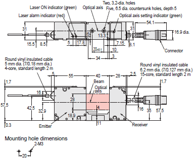
Sensor Head
Separate type: ZX-GT28S11/-GT28S41
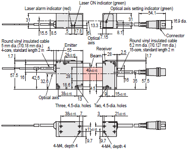
Integrated type: ZX-GT2840S11/-GT2840S41
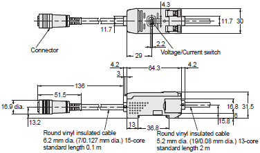
Controller
ZX-GTC11/-GTC41
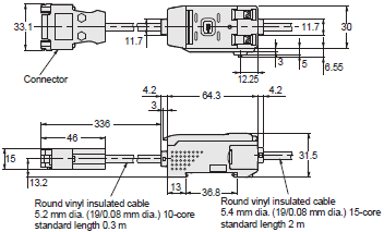
Interface Unit
ZX-GIF11/-GIF41
Calculating Unit
ZX-CAL2
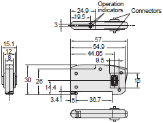
Receiver-Controller Extension Cable
ZX-XGC[]A/-XGC[]R

*1. ZX-XGC1A/R: 1M
ZX-XGC2A/R: 2M
ZX-XGC5A/R: 5M
ZX-XGC8A/R: 8M
ZX-XGC20A/R: 20M
*2. Standard cable: 6.2 dia.
Flexible cable: 6.1 dia.
last update: May 23, 2013
OMRON ZX-GT specification
ZX-GT Smart Sensor (Wide Laser Beam CCD Measurement Sensor)/Specificationslast update: June 08, 2016
Sensor Head
| Model | ZX-GT28S11 | ZX-GT2840S11 | ZX-GT28S41 | ZX-GT2840S41 |
|---|---|---|---|---|
| Output type | NPN | PNP | ||
| Appearance | Separate type | Integrated type | Separate type | Integrated type |
| Light source | Visible semiconductor laser diode (wavelength 650 nm, CLASS 1 of EN60825-1/ IEC60825-1, CLASS II of FDA (21CFR 1040.10 and 1040.11) | |||
| Measuring width | 28 mm | |||
| Sensing distance | 0 to 500 mm | 40 mm | 0 to 500 mm | 40 mm |
| Minimum sensing object | 0.5 mm dia. *1 | 0.2 mm dia. | 0.5 mm dia. *1 | 0.2 mm dia. |
| Linearity | ±0.1%F.S. *2 | |||
| Resolution | 10 μm (number of process values to average: 16) *3 | |||
| Temperature characteristic | 0.01%F.S/°C *4 | |||
| Indicators (emitter) | Laser ON indicator (green), laser alarm indicator (red) | |||
| Indicators (receiver) | Optical axis setting indicator (green) | |||
| Laser OFF input/sync input | ON: Short-circuited with 0 V or 1.5 V max. OFF: Open (leakage current: 0.1 mA max.) | ON: Short-circuited with power supply voltage or power supply voltage -1.5 V max. OFF: Open (leakage current: 0.1 mA max.) | ||
| Laser deterioration alarm output | NPN open-collector output 30 VDC 20 mA max. Residual voltage 1.2 V max. | PNP open-collector output 30 VDC 20 mA max. Residual voltage 2 V max. | ||
| Power consumption (emitter) | 30 mA max. | |||
| Power supply voltage (emitter) | 24 VDC +10%, -15% ripple (p-p) 10% max. | |||
| Dielectric strength | 1,000 VAC, 50/60 Hz for 1 min | |||
| Insulation resistance | 20 MΩ (at 500 VDC) | |||
| Operating ambient illumination (emitter) | 3,000 lx (incandescent light) | |||
| Operating ambient illumination (receiver) | 1,000 lx (incandescent light) *5 | |||
| Ambient temperature | Operating: 0 to 40°C Storage: -15 to 50°C (with no icing or condensation) | |||
| Ambient humidity | Operating and storage: 35% to 85% (with no condensation) | |||
| Vibration resistance (durability) | 10 to 150 Hz Single-amplitude: 0.75 mm for 80 min each in X, Y and Z directions | |||
| Shock resistance (durability) | 300 m/s2 3 times each in six directions (up/down, left/right, forward/backward) | |||
| Degree of protection | IEC60529 IP40 | |||
| Cable length | 2 m | |||
| Material | Case: aluminum die-cast, Lens: glass | |||
| Weight (packed state) | Approx. 550 g | Approx. 570 g | Approx. 550 g | Approx. 570 g |
| Accessories | Laser warning labels, Instruction Sheet | |||
F.S.: 28 mm measuring range of receiver
*1. Distance between emitter and receiver: 500 mm, measurement object at 250 mm from receiver.
Glass ends of chamfer 0.1 mm or more can be detected in glass edge measurement mode. (at binary level 70%)
*2. Linearity is given to be a typical error with respect to an ideal straight line when the distance between the emitter
and receiver is 100 mm and light is blocked at a distance of 50 mm from the receiver.
(On the ZX-GT2840[][], the measurement object is measured at a distance of 20 mm from the receiver.)
*3. The amount of fluctuation (±3σ) in the analog output when the distance between the emitter and receiver is 100 mm
and a ZX-GTC[][] is connected
*4. Change in the light cutoff value on one side when the distance between the emitter and receiver is 100 mm and the
light is half-cutoff at a distance of 50 mm from the receiver
(On the ZX-GT2840[][], the measurement object is measured at a distance of 20 mm from the receiver.)
*5. Standard mode (NORM) used
Controller
| Model | ZX-GTC11 | ZX-GTC41 | |
|---|---|---|---|
| Output type | NPN | PNP | |
| Measurement cycle *1 | 1.5 ms (standard mode (NORM)) 0.5 ms (high-speed mode (FAST)) *2 | ||
| Samples to average | 1/2/4/8/16/32/64/128/256/512/1,024/2,048/4,096 | ||
| Analog output *3 | For current output: 4 to 20 mA/F.S., max. load resistance 300 Ω For voltage output: ±4 V, (±5 V, 1 to 5 V *4), output impedance 100 Ω | ||
| Timing input, bank switching input, zero reset input, reset input | ON: short-circuited with 0 V or 1.5 V max. OFF: Open (leakage current: 0.1 mA max.) | ON: short-circuited with power supply voltage or power supply voltage .1.5 V max. OFF: Open (leakage current: 0.1 mA max.) | |
| HIGH/PASS/LOW Judgment output *5 Sync output *6 | NPN open-collector output 30 VDC 50 mA max. Residual voltage 1.2 V max. | PNP open-collector output 30 VDC 50 mA max. Residual voltage 2 V max. | |
| Indicator | Judgment output indicator: HIGH (orange), PASS (green), LOW (orange) Main display (red) Sub-display (yellow) Bank 1/2 (orange), zero reset (green) | ||
| Main functions | Number of registered setups | 2 banks | |
| Measurement Mode | Interrupted beam width measurement, incident beam width measurement, outer diameter measurement, center position measurement, IC lead pitch, IC lead width judgment, specified edge measurement, wire position measurement, glass edge position measurement | ||
| Display during measurement | Measured value, resolution, threshold, voltage output value, current output value (number of display digits can be changed) | ||
| Zero reset functions | Offset setting of zero reset value, zero reset value memory | ||
| Hold | Sample hold, peak hold, bottom hold, peak-to-peak hold, average hold, delay hold | ||
| Timer functions | ON delay, OFF delay, one-shot | ||
| Adjustment functions | Optical Axis adjust mode/light intensityt writing mode, variable binary level, variable edge filter, analog output scaling | ||
| Calculation | 2 Possible on up to two Controllers (Calculation Unit ZX-CAL2 is required for connecting Controllers to each other.) A-B, A+B, width | ||
| Other | Measurement cycle setting, threshold setting, hysteresis setting, initialization, key lock | ||
| Temperature characteristic | 0.005%F.S./°C | ||
| Current consumption | 150 mA max. with power supply voltage of 24 VDC (including receiver) *7 | ||
| Power supply voltage | 24 VDC +10%, .15% ripple (p-p) 10% max. | ||
| Dielectric strength | 1,000 VAC, 50/60 Hz for 1 min | ||
| Insulation resistance | 20 MΩ (at 500 VDC) | ||
| Ambient temperature | Operating: 0 to 50°C Storage: .15 to 60°C (with no icing or condensation) | ||
| Ambient humidity | Operating and storage: 35% to 85% (with no condensation) | ||
| Vibration resistance (durability) | 10 to 150 Hz Single-amplitude: 0.35 mm for 80 min each in X, Y and Z directions | ||
| Shock resistance (durability) | 300 m/s2 3 times each in six directions (up/down, left/right, forward/backward) | ||
| Degree of protection | IEC60529 IP20 | ||
| Cable length | 2 m | ||
| Material | Case: PBT (polybutylene terephthalate), Cover: Polycarbonate | ||
| Weight (packed state) | Approx. 330 g | ||
| Accessories | Instruction Sheet | ||
*1. A simple average is used in IC lead pitch judgment mode or IC lead width judgment mode.
The measurement cycle time can be calculated as follows: Specified measurement cycle time × (Number of samples
to average + 1) + 1 ms max.
In other measurement modes, a moving average is used. The first measurement cycle time can be calculated as
follows: Specified measurement cycle time × (Number of samples to average + 1) + 1 ms max. The second and
later measurement cycle times will be equal to the specified measurement cycle time.
*2. The response time in the high-speed mode (FAST) for the IC lead pitch and IC lead width judgment modes is 1 ms.
*3. Current/voltage can be switched using the switch provided on the rear of the Controller.
*4. Can be set by the analog output scaling function.
*5. The error (ERR) state is displayed when all HIGH/PASS/LOW outputs turn OFF.
*6. Normally, wire the sync output wire directly to the emitter’s sync input wire and run the Controller in the standard
mode. On an NPN type Controller, use an NPN type emitter, and on a PNP type Controller, use a PNP type emitter.
Wiring of the sync wires is not required when the Controller is run in the high-speed mode.
(Note, however, that the Controller becomes more susceptible to the influence of ambient light in this case.)
*7. The value is 175 mA max. (including receiver) when current output is set.
Interface Unit
| Model | ZX-GIF11/-GIF11A | ZX-GIF41/-GIF41A |
|---|---|---|
| Compatible Controller | ZX-GTC11 | ZX-GTC41 |
| Indicator | Power ON (green), Controller communications (orange), Controller communications error (red), RS-232C communications (orange), RS-232C communications error (red), binary output (orange) | |
| Communications port | RS-232C (9-pin D-sub connector) | |
| 12-bit binary output (D11 to D0, GATE) | NPN open-collector output 30 VDC 20mA max. Residual voltage 1.2 V max. | PNP open-collector output 30 VDC 20 mA max. Residual voltage 2 V max. |
| Power supply voltage | Supplied from Controller (power consumption: 60 mA max.) | |
| Dielectric strength | 1,000 VAC, 50/60 Hz for 1 min | |
| Insulation resistance | 20 MΩ (at 500 VDC) | |
| Ambient temperature | Operating: 0 to 50°C Storage: .15 to 60°C (with no icing or condensation) | |
| Ambient humidity | Operating and storage: 35% to 85% (with no condensation) | |
| Vibration resistance (durability) | 10 to 150 Hz Single-amplitude: 0.35 mm for 80 min each in X, Y and Z directions | |
| Shock resistance (durability) | 300 m/s2 3 times each in six directions (up/down, left/right, forward/backward) | |
| Degree of protection | IEC60529 IP20 | |
| Cable length | RS-232C 0.5 m, binary output 2 m | |
| Materials | Case: PBT (polybutylene terephthalate), Cover: Polycarbonate | |
| Weight (packed state) | ZX-GIF[]1A: Approx. 550 g ZX-GIF[]1: Approx. 330 g | |
| Accessories | ZX-GIF[]1A: Setup Software (CD-ROM), 2 clamps, Instruction Sheet ZX-GIF[]1: 2 clamps, Instruction Sheet | |
last update: June 08, 2016
OMRON ZX-GT lineup
ZX-GT Smart Sensor (Wide Laser Beam CCD Measurement Sensor)/Lineuplast update: May 23, 2013
Sensors
Sensor Head
| Appearance | Optical system | Measuring width | Sensing distance | Resolution | Output type | Model |
|---|---|---|---|---|---|---|
Emitter and receiver, separate type | Through- beam | 28 mm | 0 to 500 mm | 10μm | NPN | ZX-GT28S11 |
| PNP | ZX-GT28S41 | |||||
Emitter and receiver, integrated type | 40 mm | NPN | ZX-GT2840S11 | |||
| PNP | ZX-GT2840S41 |
Controller
| Appearance | Power supply | Output type | Model |
|---|---|---|---|
 | DC | NPN | ZX-GTC11 |
| PNP | ZX-GTC41 |
Accessories (Order Separately)
These are not included with the sensor and controller, so order these accessories separately if necessary.
Set: Interface Unit (RS-232C/Binary output) and PC Setup Software
| Output type | Model |
|---|---|
| NPN | ZX-GIF11A |
| PNP | ZX-GIF41A |
Interface Unit (RS-232C/Binary output)
| Appearance | Power supply | Output type | Model |
|---|---|---|---|
 | DC | NPN | ZX-GIF11 |
| PNP | ZX-GIF41 |
Setup software PCs
| Name | Model |
|---|---|
| Smart Monitor GT | ZX-GSW11 |
Calculating Units
| Appearance | Model |
|---|---|
 | ZX-CAL2 |
Receiver-Controller Extension Cable
| Cable length | Model | Quantity | |
|---|---|---|---|
| Standard cable | Flexible cable | ||
| 1 m | ZX-XGC1A | ZX-XGC1R | 1 |
| 2 m | ZX-XGC2A | ZX-XGC2R | |
| 5 m | ZX-XGC5A | ZX-XGC5R | |
| 8 m | ZX-XGC8A | ZX-XGC8R | |
| 20 m | ZX-XGC20A | ZX-XGC20R | |
Note: Up to two extension cables can be connected.
However, be sure to limit the total extension cable length between the receiver and the Controller to 30 meters
(including the receiver cable).
last update: May 23, 2013
- NO. ZX-GT
- TYPE:Displacement Sensors / Measurement Sensors Measurement Sensors
 Copyright Statement
 - DATE:2021-06-12
- Associated products:
ZG2 Smart Sensor (2D Measurement Sensor)/Features E4PA-N Ultrasonic Displacement Sensor/Features