
OMRON S8JXPower Supplies / In Addition/ Power Supplies/Switch mode power supplies
OMRON S8JX Power Supplies / In Addition
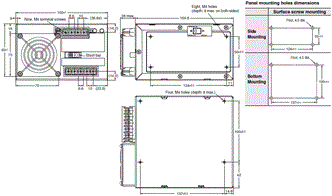
- S8JX Switch Mode Power Supply (15/35/50/100/150/300/600-W Models)/Dimensions
- S8JX Switch Mode Power Supply (15/35/50/100/150/300/600-W Models)/Catalog
- S8JX Switch Mode Power Supply (15/35/50/100/150/300/600-W Models)/Specifications
- S8JX Switch Mode Power Supply (15/35/50/100/150/300/600-W Models)/Lineup
- Purchase the OMRON S8JX Switch mode power supplies
OMRON S8JX Dimensions
/Images/l_1989-25-119015-198x198.jpglast update: December 20, 2012
Higher S8JX Series Value with New Models with EMI Class B and PFC
The exceptionally easy-to-use and popular S8JX Series now includes models with harmonic current suppression. That means more variations for a wider range of selections.
S8JX-G
General-purpose Power Supplies that are exceptionally easy to use and feature a short body.
Two Mounting Methods for Easy Installation
Install even 300-W models with either screws or DIN Rail.

* Screw mounting must be used with 600-W models.
* For 300-W models, use steel DIN Rail.
Use DC Input (80 to 370 VDC)
Use the S8JX as a 15-W to 150-W DC/DC Power Supply.
* Not applicable to 150-W, 5-V models.
The Shortest Body Class in the Industry
Thinner panels can be achieved without interfering with other components.
Comparison to Previous OMRON 50-W Front-mounting Models

300-W Models Have No Fans
* (24V/48V)

S8JX-P
Harmonic current suppression enables a wider range of application.
Functions for Export Equipment Bound for the EU
Harmonic Suppression/PFC (Power Facter Correction)
EMI Class B Compliant
More High-capacity Applications
* Applies to 300-W and 600-W models only.
Remote Sensing
You can compensate for voltage drops on the load lines.
Remote Control
Use an external signal to turn the output ON and OFF while the input voltage is applied.
Alarm Output
Output a signal for Power Supply errors, such as fan failure or insufficient voltage.
SEMI F47 Compatibility for 300-W and 600-W Models
(For 200-V Input)
Ensure reliable operation even for momentary drops in the input voltage.
Applications include semiconductor manufacturing equipment.
Slim Body for Greater Equipment Downsizing
100-W Models

300-W Models

* S8JX-P 300-W model with fan.
last update: December 20, 2012
Purchase the OMRON Switch mode power supplies Please fill in the following
If you have just landed here, this product OMRON S8JX Power Supplies / In Addition,Power Supplies / In Addition is offered online by Tianin FLD Technical Co.,Ltd. This is an online store providing Power Supplies / In Addition at wholesale prices for consumers. You can call us or send enquiry, we would give you the prices, packing,deliverty and more detailed information on the S8JX We cooperate with DHL,TNT,FEDEX,UPS,EMS,etc.They guarantee to meet your needs in terms of time and money,even if you need your OMRON S8JXPower Supplies / In Addition tomorrow morning (aka overnight or next day air) on your desk, 2, 3 days or more.Note to international customers, YES, we ship worldwide.
TL-N / -Q Rectangular Standard Proximity Sensor/Features
V780 Series UHF RFID System/Features
CS1W-PTS SYSMAC CS-series Process Analog I/O Units/Features
GT1-AD / DA Analog I/O Units/Features
XS5 NEXT Series Round Oil-resistant Connectors (M12 Smartclick)/Features
OMRON S8JX dimension
S8JX Switch Mode Power Supply (15/35/50/100/150/300/600-W Models)/Dimensionslast update: March 10, 2016
S8JX-G
Front-mounting Models
S8JX-G015[][] (15 W)
S8JX-G015[][]C (15 W)
S8JX-G035[][] (35 W)
S8JX-G035[][]C (35 W)
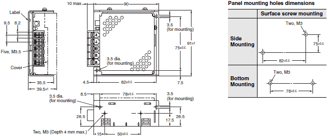
S8JX-G050[][] (50 W)
S8JX-G050[][]C (50 W)
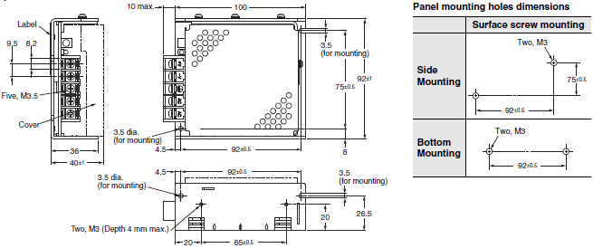
S8JX-G100[][] (100 W)
S8JX-G100[][]C (100 W)
S8JX-G15024 (150 W)
S8JX-G15024C (150 W)
S8JX-G15048 (150 W)
S8JX-G15048C (150 W)
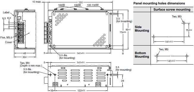
S8JX-G15005 (150 W)
S8JX-G15005C (150 W)
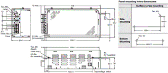
S8JX-G15012 (150 W)
S8JX-G15012C (150 W)
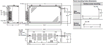
S8JX-G30005C (300 W)
S8JX-G30012C (300 W)
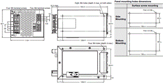
S8JX-G30024C (300 W)
S8JX-G30048C (300 W)
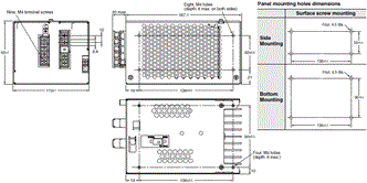
S8JX-G60005[] (600 W)
S8JX-G60012[] (600 W)
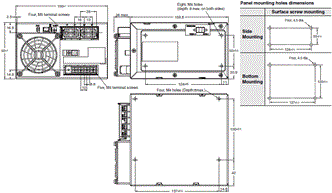
S8JX-G60024C (600 W)
S8JX-G60048C (600 W)
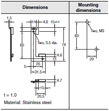
Mounting Bracket Provided with Front-mounting Power Supplies (A)
15-/35-/50-/100-/150-W Models
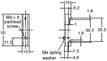
S82Y-J00F Front-mounting Bracket
Front-mounting Method
Temporarily attach the enclosed mounting bracket as shown in the illustration on the right, hook the holes (parts a) in the Power Supply on hooks on the mounting bracket (parts b), and secure the Power Supply with two mounting screws.
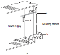
Note: Mounting screws are not provided.
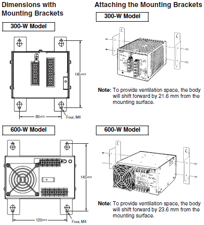
300-/600-W Models
Front-mounting Bracket (S82Y-J30F)

Note: Mounting Brackets are provided in a set, one for the right side and one for the left side.
Separately purchasable mounting brackets
(Please ask your dealer for details of delivery.)
For 30-W/50-W/100-W/150-W/300-W/600-W models (separately purchasable)
Bracket for changeover from S82J-series
The mounting-hole pitch of mounting brackets A - I below is identical to that of our product S82J. These brackets can be used for switchover with the S82J-series.
Note:Mounting brackets (A, B, C, D, E, F, G, H, I) are compatible with S82J mounting holes.
Mounting Bracket A
S82Y-JX05B
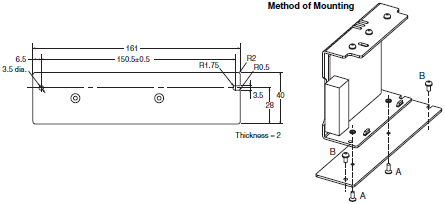
Screws used
A: Accessories (2 locations)
Be sure to use the accessory screws.
Mounting screw tightening torque (recommended): 0.49 Nm
B: M3 (2 locations)
Mounting Bracket B
S82Y-JX10B
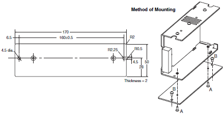
Screws used
A: Accessories (2 locations)
Be sure to use the accessory screws.
Mounting screw tightening torque (recommended): 0.49 Nm
B: M4 (2 locations)
Mounting Bracket C
S82Y-JX15B
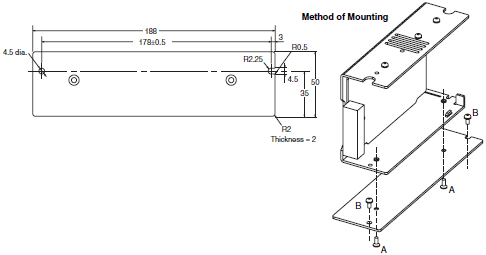
Screws used
A: Accessories (2 locations)
Be sure to use the accessory screws.
Mounting screw tightening torque (recommended): 0.49 Nm
B: M4 (2 locations)
Mounting Bracket D
S82Y-JX15F
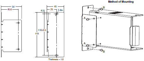
Screws used
A: Accessories (2 locations)
Be sure to use the accessory screws.
Mounting screw tightening torque (recommended): 0.49 Nm
B: M4 (2 locations)
Mounting Bracket E
S82Y-JX03B
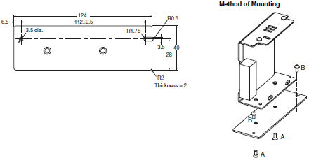
Screws used
A: Accessories (2 locations)
Be sure to use the accessory screws.
Mounting screw tightening torque (recommended): 0.49 Nm
B: M3 (2 locations)
Mounting Bracket F
S82Y-JX30B
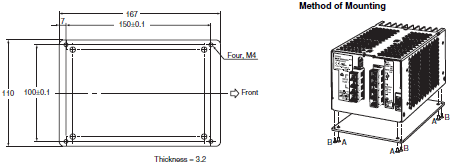
Screws used
A: Accessories (4 locations)
Be sure to use the accessory screws.
B: M4 (4 locations)
Screws of a length that will not project beyond the fixture (thickness: 3.2 mm) should be selected.
Mounting Bracket G
S82Y-JX30F

Screws used
A: Accessories (4 locations)
Be sure to use the accessory screws.
Note: For ventilation of the back surface, the body should be placed 21.6 mm in front of the mounting side.
Mounting Bracket H
S82Y-JX60B
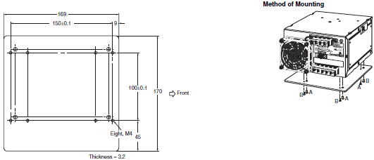
Screws used
A: Accessories (4 locations)
Be sure to use the accessory screws.
B: M4 (4 locations)
Screws of a length that will not project beyond the fixture (thickness: 3.2 mm) should be selected. (Although there
are 8 holes in the bracket body, only 4 of these are used.)
Mounting Bracket I
S82Y-JX60F

Screws used
A: Accessories (4 locations)
Be sure to use the accessory screws.
Note: For ventilation of the back surface, the body should be placed 23.6 mm in front of the mounting side.
DIN Rail-mounting Models
S8JX-G015[][]D (15 W)
S8JX-G015[][]CD (15 W)
S8JX-G035[][]D (35 W)
S8JX-G035[][]CD (35 W)
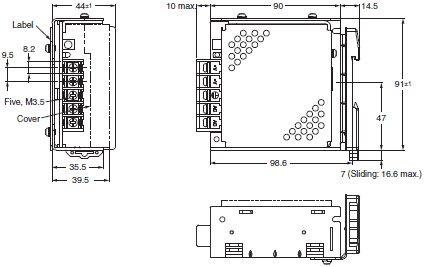
S8JX-G050[][]D (50 W)
S8JX-G050[][]CD (50 W)
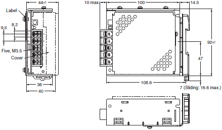
S8JX-G100[][]D (100 W)
S8JX-G100[][]CD (100 W)
S8JX-G15024D (150 W)
S8JX-G15024CD (150 W)
S8JX-G15048D (150 W)
S8JX-G15048CD (150 W)
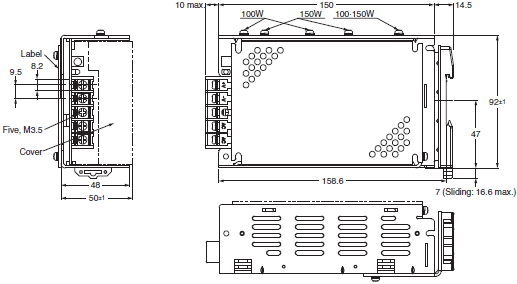
S8JX-G15005D (150 W)
S8JX-G15005CD (150 W)
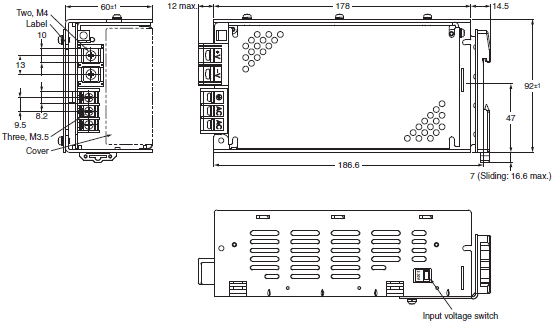
S8JX-G15012D (150 W)
S8JX-G15012CD (150 W)
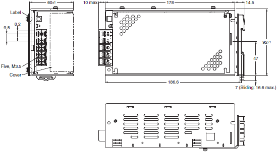
S8JX-G30005CD (300W)
S8JX-G30012CD (300W)
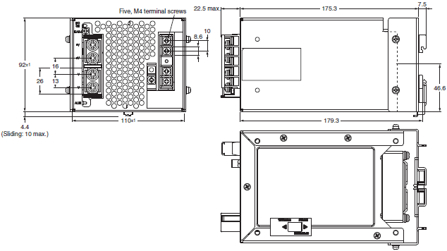
Note: Use a metal DIN Rail when mounting a 300-W model to a DIN Rail.
S8JX-G30024CD (300 W)
S8JX-G30048CD (300 W)
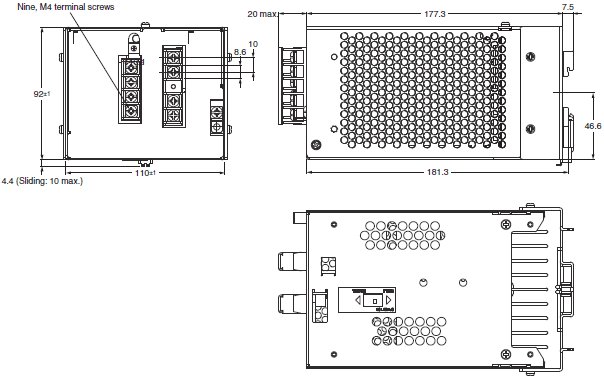
Note: Use a metal DIN Rail when mounting a 300-W model to a DIN Rail.
DIN Rail (Order Separately)
Mounting Rail (Material: Aluminum)

* Value in parentheses are for PFP-50N.
Mounting Rail (Material: Aluminum)

End Plate
Note: 1. If there is a possibility that the Unit will be subject to vibration or shock, use a steel DIN Rail. Otherwise, metallic
filings may result from aluminum abrasion. 2. If the Unit may be subjected to sliding to either side, attach an End Plate (model PFP-M) on each side of the
Unit.
S8JX-P
Front-mounting Models
S8JX-P050[][] (50 W)
S8JX-P050[][]C (50 W)
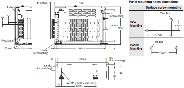
S8JX-P100[][] (100 W)
S8JX-P100[][]C (100 W)
S8JX-P15012 (150 W)
S8JX-P15012C (150 W)
S8JX-P15024 (150 W)
S8JX-P15024C (150 W)
S8JX-P15048 (150 W)
S8JX-P15048C (150 W)
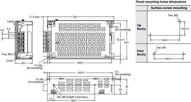
S8JX-P15005 (150 W)
S8JX-P15005C (150 W)
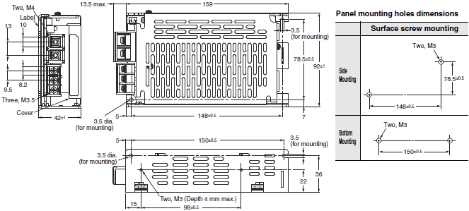
S8JX-P300[][]C (300 W)
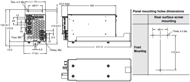
S8JX-P300[][]N (300 W)
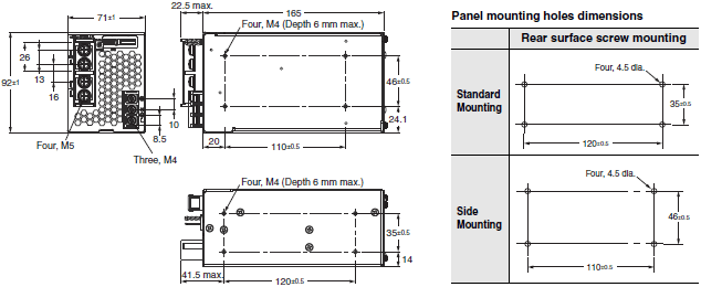
S8JX-P600[][]C (600 W)
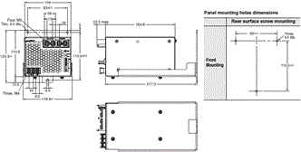
S8JX-P600[][]N (600 W)
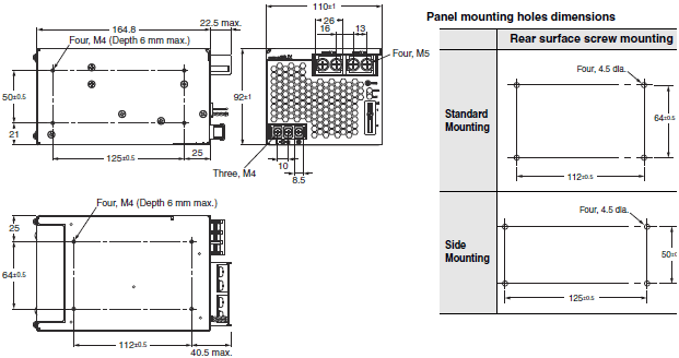
DIN Rail-mounting Models
S8JX-P050[][]D (50 W)
S8JX-P050[][]CD (50 W)
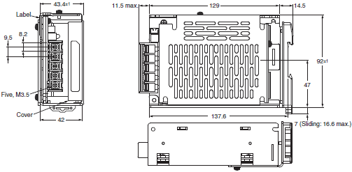
S8JX-P100[][]D (100 W)
S8JX-P100[][]CD (100 W)
S8JX-P15012D (150 W)
S8JX-P15012CD (150 W)
S8JX-P15024D (150 W)
S8JX-P15024CD (150 W)
S8JX-P15048D (150 W)
S8JX-P15048CD (150 W)
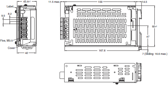
S8JX-P15005D (150 W)
S8JX-P15005CD (150 W)
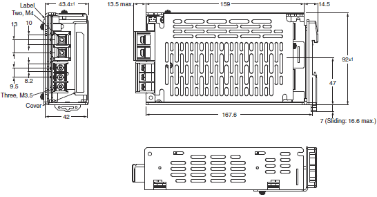
S8JX-P300[][]CD (300 W)
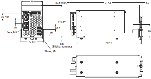
Note: Use a metal DIN Rail when mounting a 300-W model to a DIN Rail.
S8JX-P600[][]CD (600 W)
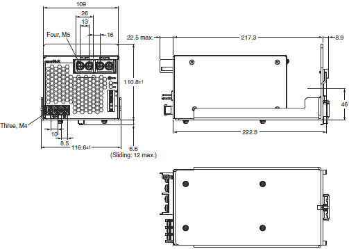
Note: Use a metal DIN Rail when mounting a 600-W model to a DIN Rail.
Mounting Bracket Provided with Front-mounting Power Supplies (A)
50-/100-/150-W Models
S82Y-J00F Front-mounting Bracket
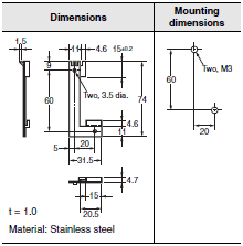
Front-mounting Method
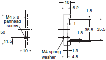
Temporarily attach the enclosed mounting bracket as shown in the illustration on the right, hook the holes (parts a) in the Power Supply on hooks on the mounting bracket (parts b), and secure the Power Supply with two mounting screws.
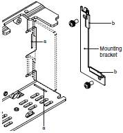
Note: Mounting screws are not provided.
DIN Rail (Order Separately)
Mounting Rail (Material: Aluminum)

* Value in parentheses are for PFP-50N.
Mounting Rail (Material: Aluminum)

End Plate
Note: 1. If there is a possibility that the Unit will be subject to vibration or shock, use a steel DIN Rail. Otherwise, metallic
filings may result from aluminum abrasion. 2. If the Unit may be subjected to sliding to either side, attach an End Plate (model PFP-M) on each side of the
Unit.
last update: March 10, 2016
OMRON S8JX catalog
S8JX Switch Mode Power Supply (15/35/50/100/150/300/600-W Models)/Catalog- Catalog
- Manual
- CAD
English
Global Edition
| Catalog Name | Catalog Number [size] | Last Update | |
|---|---|---|---|
| | T041-E1-08 [12869KB] | Apr 02, 201820180402 | S8JX Data Sheet |
| | T216-E1-01 [4336KB] | Aug 09, 201820180809 | S8JX-N/S8JX-G Series Replacement Brackets |
| | T217-E1-01 [4233KB] | Aug 09, 201820180809 | S8JX-P Series Replacement Brackets |
OMRON S8JX specification
S8JX Switch Mode Power Supply (15/35/50/100/150/300/600-W Models)/Specificationslast update: December 20, 2012
S8JX-G
Ratings, Characteristics, and Functions
| Input specification | 100 to 240 V input | |||
|---|---|---|---|---|
| Power ratings *1 | 15 W | 35 W | ||
| Efficiency | 68% min. | 73% min. | ||
| Input | Voltage *2 | 100 to 240 VAC (allowable range: 85 to 264 VAC, 80 to 370 VDC *9) | ||
| Frequency *2 | 50/60 Hz (47 to 450 Hz) | |||
| Current *3 | 100 V input | 0.4 A max. | 1 A max. | |
| 200 V input | 0.25 A max. | 0.6 A max. | ||
| Harmonic current emissions | --- | |||
| Leakage current *3 | 100 V input | 0.5 mA max. | ||
| 200 V input | 1 mA max. | |||
| Inrush current (for a cold start at 25 °C) *3 | 100 V input | 20 A max. | ||
| 200 V input | 40 A max. | |||
| Output *4 | Voltage adjustment range *5 | - 10% to 15% (with V. ADJ) (48-V models: ± 10%) | ||
| Ripple *3 | 2% (p-p) max. | |||
| Input variation influence | 0.4% max. with AC input voltage | |||
| Load variation influence | 0.8% max. (0 to 100% load, rated input voltage) | |||
| Temperature variation influence | 0.05%/ °C max. (at rated input and output) | |||
| Startup time | 500 ms max. (up to 90% of output voltage at rated input and output) | |||
| Hold time *3 | 20 ms min. | |||
| Addi- tional func- tions | Overload protection *6 | 105% to 175% of rated load current, voltage drop, intermittent, automatic reset | ||
| Overvoltage protection *7 | Yes | |||
| Overheat protection | No | |||
| Parallel operation | No (However, backup operation is possible; external diodes required.) | |||
| Series operation | Yes (For up to two Power Supplies; external diodes required.) | |||
| Protective circuit operation indicator | No | |||
| Other | Ambient operating temperature | Refer to the derating curve in Engineering Data on Catalog (with no icing or condensation). | ||
| Storage temperature | - 25 to 65 °C (with no icing or condensation) | |||
| Ambient operating humidity | 25% to 85% (Storage humidity: 25% to 90%) | |||
| Dielectric strength | 3.0 kVAC for 1 min. (between all inputs and outputs; detection current: 20 mA) 2.0 kVAC for 1 min. (between all inputs and PE terminals; detection current: 20 mA) 1.0 kVAC for 1 min. (between all outputs and PE terminals; detection current: 20 mA) | |||
| Insulation resistance | 100 MΩ min. (between all outputs and all inputs/PE terminals) at 500 VDC | |||
| Vibration resistance | 10 to 55 Hz, 0.375-mm single amplitude for 2 h each in X, Y, and Z directions | |||
| Shock resistance | 150 m/s2 , 3 times each in ± X, ± Y, ± Z directions | |||
| Output indicator | Yes (Color: Green) | |||
| EMI | Conducted Emissions | Conforms to EN 55011 Group 1 Class A and based on FCC Class A *9 | ||
| Radiated Emissions | Conforms to EN 55011 Group 1 Class A *9 | |||
| EMS | Electrostatic Discharge | Conforms to EN61000-4-2 | ||
| Radiated Electromagnetic Field | Conforms to EN61000-4-3 | |||
| Electrical Fast Transient/Burst | Conforms to EN61000-4-4 | |||
| Surge | Conforms to EN61000-4-5 | |||
| Conducted Disturbance | Conforms to EN61000-4-6 | |||
| Voltage Dips/Short Interruptions | Conforms to EN61000-4-11 | |||
| Approved standards *9 | UL Listed: UL 508 (Listing), UL UR: UL 60950-1 (Recognition) | |||
| cUL Listed: CSA C22.2 No.107.1 cUR: CSA C22.2 No. 60950-1 | ||||
| EN/VDE: EN50178 (= VDE 0160) Over voltage category III, EN 60950-1 (= VDE 0805 Teil 1) (Terminal block: Based on DIN 50274 (VDE 0660-514)) | ||||
| SEMI | SEMI F47-0200 (200-VAC input) | |||
| Weight *8 | 250 g max. | |||
| Input specification | 100 to 240 V input | |||
|---|---|---|---|---|
| Power ratings *1 | 50 W | 100 W | ||
| Efficiency | 5 V Models | 76% min. | 76% min. | |
| 12 V Models | 81% min. | 81% min. | ||
| 24 V Models | 83% min. | 83% min. | ||
| 48 V Models | 82% min. | 83% min. | ||
| Input | Voltage *2 | 100 to 240 VAC (allowable range: 85 to 264 VAC, 80 to 370 VDC *9) | ||
| Frequency *2 | 50/60 Hz (47 to 450 Hz) | |||
| Current *3 | 100 V input | 1.4 A max. | 2.5 A max. | |
| 200 V input | 0.8 A max. | 1.5 A max. | ||
| Harmonic current emissions | --- | |||
| Leakage current *3 | 100 V input | 0.5 mA max. | ||
| 200 V input | 1 mA max. | |||
| Inrush current (for a cold start at 25 °C) *3 | 100 V input | 20 A max. | ||
| 200 V input | 40 A max. | |||
| Output *4 | Voltage adjustment range *5 | - 10% to 15% (with V. ADJ) (48-V models: ± 10%) | ||
| Ripple *3 | 2% (p-p) max. | |||
| Input variation influence | 0.4% max. with AC input voltage | |||
| Load variation influence | 0.8% max. (0 to 100% load, rated input voltage) | |||
| Temperature variation influence | 0.05%/ °C max. (at rated input and output) | |||
| Startup time | 500 ms max. (up to 90% of output voltage at rated input and output) | |||
| Hold time *3 | 20 ms min. | |||
| Addi- tional func- tions | Overload protection *6 | 105% to 175% of rated load current, voltage drop, intermittent, automatic reset | ||
| Overvoltage protection *7 | Yes | |||
| Overheat protection | No | |||
| Parallel operation | No (However, backup operation is possible; external diodes required.) | |||
| Series operation | Yes (For up to two Power Supplies; external diodes required.) | |||
| Protective circuit operation indicator | No | |||
| Other | Ambient operating temperature | Refer to the derating curve in Engineering Data on Catalog (with no icing or condensation). | ||
| Storage temperature | - 25 to 65 °C (with no icing or condensation) | |||
| Ambient operating humidity | 25% to 85% (Storage humidity: 25% to 90%) | |||
| Dielectric strength | 3.0 kVAC for 1 min. (between all inputs and outputs; detection current: 20 mA) 2.0 kVAC for 1 min. (between all inputs and PE terminals; detection current: 20 mA) 1.0 kVAC for 1 min. (between all outputs and PE terminals; detection current: 20 mA) | |||
| Insulation resistance | 100 MΩ min. (between all outputs and all inputs/PE terminals) at 500 VDC | |||
| Vibration resistance | 10 to 55 Hz, 0.375-mm single amplitude for 2 h each in X, Y, and Z directions | |||
| Shock resistance | 150 m/s2 , 3 times each in ± X, ± Y, ± Z directions | |||
| Output indicator | Yes (Color: Green) | |||
| EMI | Conducted Emissions | Conforms to EN 55011 Group 1 Class A and based on FCC Class A *9 | ||
| Radiated Emissions | Conforms to EN 55011 Group 1 Class A *9 | |||
| EMS | Electrostatic Discharge | Conforms to EN61000-4-2 | ||
| Radiated Electromagnetic Field | Conforms to EN61000-4-3 | |||
| Electrical Fast Transient/Burst | Conforms to EN61000-4-4 | |||
| Surge | Conforms to EN61000-4-5 | |||
| Conducted Disturbance | Conforms to EN61000-4-6 | |||
| Voltage Dips/Short Interruptions | Conforms to EN61000-4-11 | |||
| Approved standards *9 | UL Listed: UL 508 (Listing), UL UR: UL 60950-1 (Recognition) | |||
| cUL Listed: CSA C22.2 No.107.1 cUR: CSA C22.2 No. 60950-1 | ||||
| EN/VDE: EN50178 (= VDE 0160) Over voltage category III, EN 60950-1 (= VDE 0805 Teil 1) (Terminal block: Based on DIN 50274 (VDE 0660-514)) | ||||
| SEMI | SEMI F47-0200 (200-VAC input) | |||
| Weight *8 | 300 g max. | 550 g max. | ||
| Input specification | 100/200 V switchable | 100 to 240 V input | |||
|---|---|---|---|---|---|
| Power ratings *1 | 150 W at 5 V | 150 W at 12 V | 150 W at 24 or 48 V | ||
| Efficiency | 5 V Models | 78% min. | --- | --- | |
| 12 V Models | --- | 79% min. | --- | ||
| 24 V Models | --- | --- | 86% min. | ||
| 48 V Models | --- | --- | 85% min. | ||
| Input | Voltage *2 | Switchable between 100 to 120 VAC (allowable range: 85 to 132 VAC) and 200 to 240 VAC (allowable range: 170 to 264 VAC). | 100 to 240 VAC (allowable range: 85 to 264 VAC, 80 to 370 VDC *9) | ||
| Frequency *2 | 50/60 Hz (47 to 450 Hz) | ||||
| Current *3 | 100 V input | 3.5 A max. | 3.6 A max. | 3.5 A max. | |
| 200 V input | 2.1 A max. | 2.2 A max. | 2.1 A max. | ||
| Harmonic current emissions | --- | ||||
| Leakage current *3 | 100 V input | 0.5 mA max. | |||
| 200 V input | 1 mA max. | ||||
| Inrush current (for a cold start at 25 °C) *3 | 100 V input | 20 A max. | |||
| 200 V input | 40 A max. | ||||
| Output *4 | Voltage adjustment range *5 | - 10% to 15% (with V. ADJ) (48-V models: ± 10%) | |||
| Ripple *3 | 2% (p-p) max. | ||||
| Input variation influence | 0.4% max. (with AC input voltage) | ||||
| Load variation influence | 0.8% max. (0 to 100% load, rated input voltage) | ||||
| Temperature variation influence | 0.05%/ °C max. (at rated input and output) | ||||
| Startup time | 500 ms max. (up to 90% of output voltage at rated input and output) | ||||
| Hold time *3 | 20 ms min. | ||||
| Addi- tional func- tions | Overload protection *6 | 105% to 175% of rated load current, voltage drop, automatic reset | 105% to 175% of rated load current, voltage drop, intermittent, automatic reset | ||
| Overvoltage protection *7 | Yes | ||||
| Overheat protection | No | ||||
| Parallel operation | No (However, backup operation is possible; external diodes required.) | ||||
| Series operation | Yes (For up to two Power Supplies; external diodes required.) | ||||
| Protective circuit operation indicator | No | ||||
| Other | Ambient operating temperature | Refer to the derating curve in Engineering Data on Catalog (with no icing or condensation). | |||
| Storage temperature | - 25 to 65 °C (with no icing or condensation) | ||||
| Ambient operating humidity | 25% to 85% (Storage humidity: 25% to 90%) | ||||
| Dielectric strength | 3.0 kVAC for 1 min. (between all inputs and outputs; detection current: 20 mA) 2.0 kVAC for 1 min. (between all inputs and PE terminals; detection current: 20 mA) 1.0 kVAC for 1 min. (between all outputs and PE terminals; detection current: 20 mA) | ||||
| Insulation resistance | 100 MΩ min. (between all outputs and all inputs/PE terminals) at 500 VDC | ||||
| Vibration resistance | 10 to 55 Hz, 0.375-mm single amplitude for 2 h each in X, Y, and Z directions | ||||
| Shock resistance | 150 m/s2 , 3 times each in ± X, ± Y, ± Z directions | ||||
| Output indicator | Yes (Color: Green) | ||||
| EMI | Conducted Emissions | Conforms to EN 55011 Group 1 Class A and based on FCC Class A *9 | |||
| Radiated Emissions | Conforms to EN 55011 Group 1 Class A *9 | ||||
| EMS | Electrostatic Discharge | Conforms to EN61000-4-2 | |||
| Radiated Electromagnetic Field | Conforms to EN61000-4-3 | ||||
| Electrical Fast Transient/Burst | Conforms to EN61000-4-4 | ||||
| Surge | Conforms to EN61000-4-5 | ||||
| Conducted Disturbance | Conforms to EN61000-4-6 | ||||
| Voltage Dips/Short Interruptions | Conforms to EN61000-4-11 | ||||
| Approved standards *9 | UL Listed: UL 508 (Listing), UL UR: UL 60950-1 (Recognition) | ||||
| cUL Listed: CSA C22.2 No.107.1 cUR: CSA C22.2 No. 60950-1 | |||||
| EN/VDE: EN50178 (= VDE 0160), Over voltage category III, EN 60950-1 (= VDE 0805Teil 1) (Terminal block: Based on DIN 50274 (VDE 0660-514)) | |||||
| SEMI | --- | SEMI F47-0200 (200-VAC input) | |||
| Weight *8 | 800 g max. | 700 g max. | 600 g max. | ||
*1. When a load is connected that has a built-in DC-DC converter, the overload protection may operate at startup and the
Power Supply may not start. Refer to Overload Protection on Catalog.*2. Do not use an Inverter output for the Power Supply. Inverters with an output frequency of 50/60 Hz are available, but
the rise in the internal temperature of the Power Supply may result in ignition or burning.*3. Rated input voltage: 100 or 200 VAC at 100% load.*4. Output characteristics: Specified at power supply output terminals.*5. If the output voltage adjuster (V. ADJ) is turned, the voltage will increase by more than the allowable voltage range.
When adjusting the output voltage, confirm the actual output voltage from the Power Supply and be sure that load is
not damaged.*6. For details, refer to Overload Protection on Catalog.*7. To reset the protection, turn OFF the input power for seven minutes or longer and then turn it back ON.*8. The weight indicated is for Front-mounting, Open-frame Power Supply.*9. The range for compliance with EC Directives and safety standards (UL, EN, etc.) is 100 to 240 VAC (85 to 264 VAC).
| Input specification | 100/200 V (Selected) | |||
|---|---|---|---|---|
| Power ratings *1 | 300 W | 600 W | ||
| Efficiency | 5 V models | 71% min. | 72% min. | |
| 12 V models | 75% min. | 78% min. | ||
| 24 V models | 82% min. | 80% min. | ||
| 48 V models | 82% min. | 80% min. | ||
| Input | Voltage *2 | 100 to 120 VAC (allowable range: 85 to 132 VAC) 200 to 240 VAC (allowable range: 170 to 264 VAC) (Switchable) | ||
| Frequency *2 | 50/60 Hz (47 to 450 Hz) | |||
| Current *3 | 100 V input | 8 A max. | 16 A max. (5V, 12V, 48V) 14 A max. (24V) | |
| 200 V input | 4.5 A max. | 9 A max. (5V, 12V, 48V) 8 A max. (24V) | ||
| Harmonic current emissions | --- | |||
| Leakage current *3 | 100 V input | 0.5 mA max. | ||
| 200 V input | 1 mA max. | |||
| Inrush current (for a cold start at 25 °C) *3 | 100 V input | 25 A max. | 30 A max. | |
| 200 V input | 50 A max. | 60 A max. | ||
| Output *4 | Voltage adjustment range *5 | -10% to 15% (with V. ADJ) (48-V models: ±10%) | ||
| Ripple *3 | 2.8% (p-p) max.(5V) *6 2% (p-p) max.(12V, 24V, 48V) | 3.8% (p-p) max.(5V) *6 2% (p-p) max.(12V) *6 2% (p-p) max.(24V, 48V) | ||
| Input variation influence | 0.4% max. | |||
| Load variation influence | 0.8% max. (0 to 100% load, rated input voltage) | |||
| Temperature variation influence | 0.05%/ °C max. | |||
| Startup time | 650 ms max. | 500 ms max. | ||
| Hold time *3 | 20 ms min. | |||
| Addi- tional func- tions | Overload protection *7 | 105% to 175% of rated load current, Inverted L voltage drop, the circuit will be shut OFF when the overload exceeds 5 s. (5V, 12V) *10 voltage drop, intermittent, automatic reset. (24V, 48V) | 105% to 175% of rated load current, Inverted L voltage drop, the circuit will be shut OFF when the overload exceeds 5 s. *10 | |
| Overvoltage protection *8 | Yes (5V, 12V) *10 Yes (24V, 48V) *10 | Yes *10 | ||
| Overheat protection | Yes (5V, 12V) *10 N0 (24V, 48V) *10 | Yes *10 | ||
| Parallel operation | Yes (up to 5 units) | |||
| Series operation | Yes (For up to two Power Supplies; external diodes required.) | |||
| Protective circuit operation indicator | Yes (color: red) (5V, 12V) No (24V, 48V) | Yes (color: red) | ||
| Other | Ambient operating temperature | Refer to the derating curve in Engineering Data on Catalog (with no icing or condensation). | ||
| Storage temperature | - 25 to 65 °C (with no icing or condensation) | |||
| Ambient operating humidity | 25% to 85% (Storage humidity: 25% to 90%) | |||
| Dielectric strength | 3.0 kVAC for 1 min. (between all inputs and outputs; detection current: 25 mA) 2.0 kVAC for 1 min. (between all inputs and PE terminals; detection current: 25 mA) 1.0 kVAC for 1 min. (between all outputs and PE terminals; detection current: 25 mA) | |||
| Insulation resistance | 100 MΩ min. (between all outputs and all inputs/PE terminals) at 500 VDC | |||
| Vibration resistance | 10 to 55 Hz, 0.375-mm single amplitude for 2 h each in X, Y, and Z directions | |||
| Shock resistance | 150 m/s2 , 3 times each in ± X, ± Y, ± Z directions | |||
| Output indicator | Yes (Color: Green) | |||
| EMI | Conducted Emissions *3 | Conforms to EN 55011 Group 1 Class A and based on FCC Class A *11 | ||
| Radiated Emissions | Conforms to EN 55011 Group 1 Class A *11 *12 | |||
| EMS | Electrostatic Discharge | Conforms to EN61000-4-2 | ||
| Radiated Electromagnetic Field | Conforms to EN61000-4-3 | |||
| Electrical Fast Transient/Burst | Conforms to EN61000-4-4 | |||
| Surge | Conforms to EN61000-4-5 | |||
| Conducted Disturbance | Conforms to EN61000-4-6 | |||
| Voltage Dips/Short Interruptions | Conforms to EN61000-4-11 | |||
| Approved standards *13 | UL UR: UL 508 (Recognition), UL 60950-1 (Recognition) | |||
| cUR: CSA C22.2 No. 60950-1 | ||||
| EN/VDE: EN50178 (= VDE 0160), Over voltage category III, EN 60950-1 (= VDE 0805 Teil 1) (Terminal block: Based on DIN 50274 (VDE 0660-514)) | ||||
| Weight *9 | 1,800 g max. (5V, 12V) 1,600 g max. (24V, 48V) | 2,500 g max. | ||
*1. When a load is connected that has a built-in DC-DC converter, the overload protection may operate at startup and the
Power Supply may not start. Refer to Overload Protection on Catalog.*2. Do not use an Inverter output for the Power Supply. Inverters with an output frequency of 50/60 Hz are available, but
the rise in the internal temperature of the Power Supply may result in ignition or burning.*3. Rated input voltage: 100 or 200 VAC at 100% load.*4. Output characteristics: Specified at power supply output terminals.*5. If the output voltage adjuster (V. ADJ) is turned, the voltage will increase by more than the allowable voltage range.
When adjusting the output voltage, confirm the actual output voltage from the Power Supply and be sure that load is
not damaged.*6. Measurement methods are based on JEITA standard RC-9131A. Refer to Ripple Noise Voltage on Catalog.*7. For details, refer to Overload Protection on Catalog.*8. To reset the protection, turn OFF the input power for three minutes or longer and then turn it back ON.*9. The weight indicated is for Front-mounting Power Supply.*10.The protection-ON alarm indicator will light as soon as the output is interrupted. For resetting, turn OFF the input
power, leave for more than three minutes , and then turn it back ON again.*11.Noise values depend on the wiring methods and other factors. Insert noise filters and cores in the input and output
lines. 300 W, 5 V: Two E04SR401938 (manufactured by SEIWA) on the output line. 300 W, 12 V: One E04SR401938 (manufactured by SEIWA) on the output line. 600 W, 5 V or 12 V: One FN2450G-16-61 (manufactured by Schaffner) on the input line. One E04RC613620 (manufactured by SEIWA) on the output line.*12.For the 600-W, 5-V and 12-V models, class A compliance was met with an aluminum plate placed under the Power
Supply.*13.The range for compliance with EC Directives and safety standards (UL, EN, etc.) is 100 to 240 VAC (85 to 264 VAC).
S8JX-P
Ratings, Characteristics, and Functions
| Input specification | 100 to 240 V input | ||||
|---|---|---|---|---|---|
| Power ratings *1 | 50 W | 100 W | 150 W | ||
| Efficiency | 5 V Models | 73% min. | 78% min. | 79% min. | |
| 12 V Models | 76% min. | 78% min. | 78% min. | ||
| 24 V Models | 77% min. | 81% min. | 81% min. | ||
| 48 V Models | 80% min. | 81% min. | 82% min. | ||
| Input | Voltage *2 | 100 to 240 VAC (allowable range: 85 to 264 VAC, 80 to 370 VDC *9) | |||
| Frequency *2 | 50/60 Hz (47 to 63 Hz) | ||||
| Current *3 | 100 V input | 0.75 A max. | 1.4 A max. | 2.1 A max. | |
| 200 V input | 0.4 A max. | 0.75 A max. | 1.1 A max. | ||
| Power factor | 0.9 min. | ||||
| Harmonic current emissions | Conforms to EN61000-3-2 | ||||
| Leakage current *3 | 100 V input | 0.5 mA max. | |||
| 200 V input | 1 mA max. | ||||
| Inrush current (for a cold start at 25 °C) *3 | 100 V input | 17.5 A max. | |||
| 200 V input | 35 A max. | ||||
| Output *4 | Voltage adjustment range *5 | - 10% to 15% (with V. ADJ) (48-V models: ± 10%) | |||
| Ripple *3 | 2% (p-p) max. This shall be 3% (p-p) or less when the ambient temperature is less than 0 °C (for only 5 V type). | ||||
| Input variation influence | 0.4% max. with AC input voltage | ||||
| Load variation influence | 0.8% max. (0 to 100% load, rated input voltage) | ||||
| Temperature variation influence | 0.05%/ °C max. (at rated input and output) | ||||
| Startup time | 1,000 ms max. | ||||
| Hold time *3 | 20 ms min. | ||||
| Addi- tional func- tions | Overload protection *6 | 105% to 160% of rated load current, voltage drop, intermittent, automatic reset | 105% to 160% of rated load current, voltage drop, automatic reset | ||
| Overvoltage protection *7 | Yes | ||||
| Overheat protection | No | ||||
| Parallel operation | No (However, backup operation is possible; external diodes required.) | ||||
| Series operation | Yes (For up to two Power Supplies; external diodes required.) | ||||
| Alarm indicator | No | ||||
| Other | Ambient operating temperature | Refer to the derating curve in Engineering Data on Catalog (with no icing or condensation). | |||
| Storage temperature | - 25 to 75 °C (with no icing or condensation) | ||||
| Ambient operating humidity | 25% to 85% (Storage humidity: 25% to 90%) | ||||
| Dielectric strength | 3.0 kVAC for 1 min. (between all inputs and outputs; detection current: 20 mA) 2.0 kVAC for 1 min. (between all inputs and PE terminals; detection current: 20 mA) 1.0 kVAC for 1 min. (between all outputs and PE terminals; detection current: 20 mA) | ||||
| Insulation resistance | 100 MΩ min. (between all outputs and all inputs/PE terminals) at 500 VDC | ||||
| Vibration resistance | 10 to 55 Hz, 0.375-mm single amplitude for 2 h each in X, Y, and Z directions | ||||
| Shock resistance | 150 m/s2 , 3 times each in ± X, ± Y, ± Z directions | ||||
| Output indicator | Yes (Color: Green) | ||||
| EMI | Conducted Emissions | Conforms to EN 55011 Group 1 Class B and based on FCC Class B *9 | |||
| Radiated Emissions | Conforms to EN 55011 Group 1 Class B *9 | ||||
| EMS | Electrostatic Discharge | Conforms to EN61000-4-2 | |||
| Radiated Electromagnetic Field | Conforms to EN61000-4-3 | ||||
| Electrical Fast Transient/Burst | Conforms to EN61000-4-4 | ||||
| Surge | Conforms to EN61000-4-5 | ||||
| Conducted Disturbance | Conforms to EN61000-4-6 | ||||
| Voltage Dips/Short Interruptions | Conforms to EN61000-4-11 | ||||
| Approved standards *9 | UL Listed: UL 508 (Listing), UL UR: UL 60950-1 (Recognition) | ||||
| cUL Listed: CSA C22.2 No.107.1 cUR: CSA C22.2 No. 60950-1 | |||||
| EN/VDE: EN50178 (= VDE 0160) Over voltage category III, EN 60950-1 (= VDE 0805 Teil 1) (Terminal block: Based on DIN 50274 (VDE 0660-514)) | |||||
| SEMI | SEMI F47-0706 (200-VAC input) | ||||
| Weight *8 | 370 g max. | 550 g max. | 590 g max. | ||
*1. When a load is connected that has a built-in DC-DC converter, the overload protection may operate at startup and the
Power Supply may not start. Refer to Overload Protection on Catalog.*2. Do not use an Inverter output for the Power Supply. Inverters with an output frequency of 50/60 Hz are available, but
the rise in the internal temperature of the Power Supply may result in ignition or burning.*3. Rated input voltage: 100 or 200 VAC at 100% load.*4. Output characteristics: Specified at power supply output terminals.*5. If the output voltage adjuster (V. ADJ) is turned, the voltage will increase by more than the allowable voltage range.
When adjusting the output voltage, confirm the actual output voltage from the Power Supply and be sure that load is
not damaged.*6. For details, refer to Overload Protection on Catalog.*7. To reset the protection, turn OFF the input power for three minutes or longer and then turn it back ON.*8. The weight indicated is for Front-mounting, Open-frame Power Supply.*9. The range for compliance with EC Directives and safety standards (UL, EN, etc.) is 100 to 240 VAC (85 to 264 VAC).
| Input specification | 100 to 240 V input | |||
|---|---|---|---|---|
| Power ratings *1 | 300 W | 600 W | ||
| Efficiency | 5 V Models | 75% min. | 76% min. | |
| 12 V Models | 77% min. | 76% min. | ||
| 24 V Models | 79% min. | 78% min. | ||
| 48 V Models | 78% min. | 79% min. | ||
| Input | Voltage *2 | 100 to 240 VAC (allowable range: 85 to 264 VAC, 80 to 370 VDC *8) | ||
| Frequency *2 | 50/60 Hz (47 to 63 Hz) | |||
| Current *3 | 100 V input | 4.5 A max. | 8.7 A max. | |
| 200 V input | 2.2 A max. | 4.3 A max. | ||
| Power factor | 0.9 min. | |||
| Harmonic current emissions | Conforms to EN61000-3-2 | |||
| Leakage current *3 | 100 V input | 0.5 mA max. | ||
| 200 V input | 1 mA max. | |||
| Inrush current (for a cold start at 25 °C) *3 | 100 V input | 17.5 A max. | ||
| 200 V input | 35 A max. | |||
| Output *4 | Voltage adjustment range *5 | -10% to 15% (with V. ADJ) (5 V, 48 V models: ±10%) | ||
| Ripple *3 | 2% (p-p) max. 3% (p-p) max. (for only 5 V type) *12 | |||
| Input variation influence | 0.4% max. | |||
| Load variation influence | 0.8% max. (0 to 100% load, rated input voltage) | |||
| Temperature variation influence | 0.05%/ °C max. | |||
| Startup time | 1,000 ms max. | |||
| Hold time *3 | 20 ms min. | |||
| Addi- tional func- tions | Overload protection *6 | 105% to 160% of rated load current, voltage drop, intermittent, automatic reset. | ||
| Overvoltage protection *7 | Yes | |||
| Overheat protection | Yes | |||
| Parallel operation | Yes (up to 5 Power Supplies) | |||
| Series operation | Yes (For up to two Power Supplies; external diodes required.) | |||
| Remote sensing | Supported | |||
| Remote control | Supported | |||
| Alarm detection indication | Yes (color: red) | |||
| Alarm output | Provided, open-collector output, 30 VDC max, 50 mA max. | |||
| Other | Ambient operating temperature | Refer to the derating curve in Engineering Data on Catalog. (with no icing or condensation). | ||
| Storage temperature | - 25 to 75 °C (with no icing or condensation) | |||
| Ambient operating humidity | 25% to 85% (Storage humidity: 25% to 90%) | |||
| Dielectric strength | 3.0 kVAC for 1 min. (between all inputs and outputs; detection current: 20 mA) 2.0 kVAC for 1 min. (between all inputs and PE terminals; detection current: 20 mA) 1.0 kVAC for 1 min. (between all outputs and PE terminals; detection current: 100 mA) 100 VAC for 1 min. (between all outputs and RC terminals; detection current: 100 mA) 500 VAC for 1 min. (between all outputs and ALM terminals; detection current: 20 mA) | |||
| Insulation resistance | 100 MΩ min. (between all outputs and all inputs/PE terminals) at 500 VDC | |||
| Vibration resistance | 10 to 55 Hz, 0.375-mm single amplitude for 2 h each in X, Y, and Z directions | |||
| Shock resistance | 150 m/s2, 3 times each in ±X, ±Y, ±Z directions *10 | |||
| Output indicator | Yes (Color: Green) | |||
| EMI | Conducted Emissions *3 | Conforms to EN 55011 Group 1 Class B and based on FCC Class B *11 | ||
| Radiated Emissions | Conforms to EN 55011 Group 1 Class B *11 | |||
| EMS | Electrostatic Discharge | Conforms to EN61000-4-2 | ||
| Radiated Electromagnetic Field | Conforms to EN61000-4-3 | |||
| Electrical Fast Transient/Burst | Conforms to EN61000-4-4 | |||
| Surge | Conforms to EN61000-4-5 | |||
| Conducted Disturbance | Conforms to EN61000-4-6 | |||
| Voltage Dips/Short Interruptions | Conforms to EN61000-4-11 | |||
| Approved standards *8 | UL UR: UL 508 (Recognition) *13 UL Listed: UL508 (Listing) *14 UL UR: UL 60950-1 (Recognition) | |||
| cUR: CSA C22.2 No.107.1, CSA C22.2 No. 60950-1 | ||||
| EN/VDE: EN50178 (= VDE 0160) Over voltage category III, EN 60950-1 (= VDE 0805 Teil 1) (Terminal block: Based on DIN 50274 (VDE 0660-514)) | ||||
| SEMI | SEMI F47-0706 (200-VAC input) | |||
| Weight | 1,200 g max. *9 | 1,800 g max. *9 | ||
*1. When a load is connected that has a built-in DC-DC converter, the overload protection may operate at startup and
the Power Supply may not start. Refer to Overload Protection on Catalog.*2. Do not use an Inverter output for the Power Supply. Inverters with an output frequency of 50/60 Hz are available, but
the rise in the internal temperature of the Power Supply may result in ignition or burning.*3. Rated input voltage: 100 or 200 VAC at 100% load.*4. Output characteristics: Specified at power supply output terminals.*5. If the output voltage adjuster (V. ADJ) is turned, the voltage will increase by more than the allowable voltage range.
When adjusting the output voltage, confirm the actual output voltage from the Power Supply and be sure that load is
not damaged.*6. For details, refer to Overload Protection on Catalog.*7. To reset the protection, turn OFF the input power for three minutes or longer and then turn it back ON.*8. The range for compliance with EC Directives and safety standards (UL, EN, etc.) is 100 to 240 VAC (85 to 264 VAC).*9. The weight is of the type without a mounting bracket.*10.S8JX-P600[][]CD: 100 m/s2*11.The noise value will vary depending on wiring methods and other characteristics. 300-W/600-W models conform to Class B with an aluminum plate set under the product. For the 300-W 5V and 600-W 5V and 12V models, insert a noise filter (TDK-Lambda RSEN-2016) in the input line.*12.Measurement method conform to RC-9131A of the JEITA standards. For details, refer to "Ripple Noise Voltage" on
Catalog.*13.Applicable to the 300-W/600-W 5V and 12V models*14.Applicable to the 300-W/600-W 24V and 48V models
last update: December 20, 2012
OMRON S8JX lineup
S8JX Switch Mode Power Supply (15/35/50/100/150/300/600-W Models)/Lineuplast update: April 2, 2018
S8JX-G
Note: For details on normal stock models, contact your nearest OMRON representative.
DIN Rail-mounting *

| Configuration | Input voltage | Power ratings | Output voltage (VDC) | Output current | Built-in fan | Model |
|---|---|---|---|---|---|---|
| Covered Power Supplies | 100 to 240 VAC (free) (80 to 370 VDC *) S8JX-G15005[][]: Switchable between 100 to 120 VAC and 200 to 240 VAC. (DC power cannot be input.) | 15 W | 5 V | 3 A | No | S8JX-G01505CD |
| 12 V | 1.3 A | S8JX-G01512CD | ||||
| 15 V | 1 A | S8JX-G01515CD | ||||
| 24 V | 0.65 A | S8JX-G01524CD | ||||
| 48 V | 0.35 A | S8JX-G01548CD | ||||
| 35 W | 5 V | 7 A | S8JX-G03505CD | |||
| 12 V | 3 A | S8JX-G03512CD | ||||
| 15 V | 2.4 A | S8JX-G03515CD | ||||
| 24 V | 1.5 A | S8JX-G03524CD | ||||
| 48 V | 0.75 A | S8JX-G03548CD | ||||
| 50 W | 5 V | 10 A | S8JX-G05005CD | |||
| 12 V | 4.2 A | S8JX-G05012CD | ||||
| 24 V | 2.1 A | S8JX-G05024CD | ||||
| 48 V | 1.1 A | S8JX-G05048CD | ||||
| 100 W | 5 V | 20 A | S8JX-G10005CD | |||
| 12 V | 8.5 A | S8JX-G10012CD | ||||
| 24 V | 4.5 A | S8JX-G10024CD | ||||
| 48 V | 2.1 A | S8JX-G10048CD | ||||
| 150 W | 5 V | 30 A | S8JX-G15005CD | |||
| 12 V | 13 A | S8JX-G15012CD | ||||
| 24 V | 6.5 A | S8JX-G15024CD | ||||
| 48 V | 3.3 A | S8JX-G15048CD | ||||
| 100 to 120 VAC 200 to 240 VAC (Switchable) | 300 W | 5 V | 60 A | Yes | S8JX-G30005CD | |
| 12 V | 27 A | S8JX-G30012CD | ||||
| 24 V | 14A | No | S8JX-G30024CD | |||
| 48 V | 7A | S8JX-G30048CD |
* The range for compliance with EC Directives and safety standards (UL, EN, etc.) is 100 to 240 VAC (85 to 264 VAC).
DIN Rail-mounting *

| Configuration | Input voltage | Power ratings | Output voltage (VDC) | Output current | Built-in fan | Model |
|---|---|---|---|---|---|---|
| Open type Power Supplies | 100 to 240 VAC (free) (80 to 370 VDC *) S8JX-G15005[][]: Switchable between 100 to 120 VAC and 200 to 240 VAC. (DC power cannot be input.) | 15 W | 5 V | 3 A | No | S8JX-G01505D |
| 12 V | 1.3 A | S8JX-G01512D | ||||
| 15 V | 1 A | S8JX-G01515D | ||||
| 24 V | 0.65 A | S8JX-G01524D | ||||
| 48 V | 0.35 A | S8JX-G01548D | ||||
| 35 W | 5 V | 7 A | S8JX-G03505D | |||
| 12 V | 3 A | S8JX-G03512D | ||||
| 15 V | 2.4 A | S8JX-G03515D | ||||
| 24 V | 1.5 A | S8JX-G03524D | ||||
| 48 V | 0.75 A | S8JX-G03548D | ||||
| 50 W | 5 V | 10 A | S8JX-G05005D | |||
| 12 V | 4.2 A | S8JX-G05012D | ||||
| 24 V | 2.1 A | S8JX-G05024D | ||||
| 48 V | 1.1 A | S8JX-G05048D | ||||
| 100 W | 5 V | 20 A | S8JX-G10005D | |||
| 12 V | 8.5 A | S8JX-G10012D | ||||
| 24 V | 4.5 A | S8JX-G10024D | ||||
| 48 V | 2.1 A | S8JX-G10048D | ||||
| 150 W | 5 V | 30 A | S8JX-G15005D | |||
| 12 V | 13 A | S8JX-G15012D | ||||
| 24 V | 6.5 A | S8JX-G15024D | ||||
| 48 V | 3.3 A | S8JX-G15048D |
* The range for compliance with EC Directives and safety standards (UL, EN, etc.) is 100 to 240 VAC (85 to 264 VAC).
Front-mounting *

| Configuration | Input voltage | Power ratings | Output voltage (VDC) | Output current | Built-in fan | Front- mounting bracket | Model |
|---|---|---|---|---|---|---|---|
| Covered Power Supplies | 100 to 240 VAC (free) (80 to 370 VDC *) S8JX-G15005[][]: Switchable between 100 to 120 VAC and 200 to 240 VAC. (DC power cannot be input.) | 15 W | 5 V | 3 A | No | Provided | S8JX-G01505C |
| 12 V | 1.3 A | S8JX-G01512C | |||||
| 15 V | 1 A | S8JX-G01515C | |||||
| 24 V | 0.65 A | S8JX-G01524C | |||||
| 48 V | 0.35 A | S8JX-G01548C | |||||
| 35 W | 5 V | 7 A | S8JX-G03505C | ||||
| 12 V | 3 A | S8JX-G03512C | |||||
| 15 V | 2.4 A | S8JX-G03515C | |||||
| 24 V | 1.5 A | S8JX-G03524C | |||||
| 48 V | 0.75 A | S8JX-G03548C | |||||
| 50 W | 5 V | 10 A | S8JX-G05005C | ||||
| 12 V | 4.2 A | S8JX-G05012C | |||||
| 24 V | 2.1 A | S8JX-G05024C | |||||
| 48 V | 1.1 A | S8JX-G05048C | |||||
| 100 W | 5 V | 20 A | S8JX-G10005C | ||||
| 12 V | 8.5 A | S8JX-G10012C | |||||
| 24 V | 4.5 A | S8JX-G10024C | |||||
| 48 V | 2.1 A | S8JX-G10048C | |||||
| 150 W | 5 V | 30 A | S8JX-G15005C | ||||
| 12 V | 13 A | S8JX-G15012C | |||||
| 24 V | 6.5 A | S8JX-G15024C | |||||
| 48 V | 3.3 A | S8JX-G15048C | |||||
| 100 to 120 VAC 200 to 240 VAC (Switchable) | 300 W | 5 V | 60 A | Yes | No | S8JX-G30005C | |
| 12 V | 27 A | S8JX-G30012C | |||||
| 24 V | 14A | No | S8JX-G30024C | ||||
| 48 V | 7A | S8JX-G30048C | |||||
| 600 W | 5 V | 120A | Yes | S8JX-G60005C | |||
| 12 V | 53A | S8JX-G60012C | |||||
| 24 V | 27A | S8JX-G60024C | |||||
| 48 V | 13A | S8JX-G60048C |
* The range for compliance with EC Directives and safety standards (UL, EN, etc.) is 100 to 240 VAC (85 to 264 VAC).
Front-mounting *

| Configuration | Input voltage | Power ratings | Output voltage (VDC) | Output current | Built-in fan | Front- mounting bracket | Model |
|---|---|---|---|---|---|---|---|
| Open type Power Supplies | 100 to 240 VAC (free) (80 to 370 VDC *) S8JX-G15005[][]: Switchable between 100 to 120 VAC and 200 to 240 VAC. (DC power cannot be input.) | 15 W | 5 V | 3 A | No | Provided | S8JX-G01505 |
| 12 V | 1.3 A | S8JX-G01512 | |||||
| 15 V | 1 A | S8JX-G01515 | |||||
| 24 V | 0.65 A | S8JX-G01524 | |||||
| 48 V | 0.35 A | S8JX-G01548 | |||||
| 35 W | 5 V | 7 A | S8JX-G03505 | ||||
| 12 V | 3 A | S8JX-G03512 | |||||
| 15 V | 2.4 A | S8JX-G03515 | |||||
| 24 V | 1.5 A | S8JX-G03524 | |||||
| 48 V | 0.75 A | S8JX-G03548 | |||||
| 50 W | 5 V | 10 A | S8JX-G05005 | ||||
| 12 V | 4.2 A | S8JX-G05012 | |||||
| 24 V | 2.1 A | S8JX-G05024 | |||||
| 48 V | 1.1 A | S8JX-G05048 | |||||
| 100 W | 5 V | 20 A | S8JX-G10005 | ||||
| 12 V | 8.5 A | S8JX-G10012 | |||||
| 24 V | 4.5 A | S8JX-G10024 | |||||
| 48 V | 2.1 A | S8JX-G10048 | |||||
| 150 W | 5 V | 30 A | S8JX-G15005 | ||||
| 12 V | 13 A | S8JX-G15012 | |||||
| 24 V | 6.5 A | S8JX-G15024 | |||||
| 48 V | 3.3 A | S8JX-G15048 |
* The range for compliance with EC Directives and safety standards (UL, EN, etc.) is 100 to 240 VAC (85 to 264 VAC).
Separately purchasable mounting brackets
(Please ask your dealer for details of delivery.)
For 30-W/50-W/100-W/150-W/300-W/600-W models (separately purchasable)
Bracket for changeover from S82J-series
The mounting-hole pitch of mounting brackets A - I below is identical to that of our product S82J. These brackets can be used for switchover with the S82J-series.
| Models compatible with the S82J-series | Mounting Orientation | Products names | Model |
|---|---|---|---|
| 50-W models | Underside mounting | Mounting bracket A (For S8JX-G-series 50-W models) | S82Y-JX05B |
| 100-W 24 V models | Mounting bracket B (For S8JX-G-series 100-W 24 V models) | S82Y-JX10B | |
| 100-W 5 V, 12 V, 150-W 24 V models | Mounting bracket C (For S8JX-G-series 100-W 5 V, 12V, 150 W models) | S82Y-JX15B | |
| 100-W 5 V, 12 V, 150-W 24 V models | Front mounting | Mounting bracket D (For S8JX-G-series 100-W 5 V, 12 V, 150 W models) | S82Y-JX15F |
| 25-W models | Underside mounting | Mounting bracket E (For S8JX-G-series 30-W models) | S82Y-JX03B |
| 300-W models | Underside mounting | Mounting bracket F (For S8JX-G-series 300-W models) | S82Y-JX30B |
| Front mounting | Mounting bracket G (For S8JX-G-series 300-W models) | S82Y-JX30F | |
| 600-W models | Underside mounting | Mounting bracket H (For S8JX-G-series 600-W models) | S82Y-JX60B |
| Front mounting | Mounting bracket I (For S8JX-G-series 600-W models) | S82Y-JX60F |
Note: Mounting brackets (A, B, C, D, E, F, G, H, I) are compatible with S82J mounting holes.
DIN Rail (Order Separately)
Mounting Rail
(Material: Aluminum)
| Model |
|---|
| PFP-100N |
| PFP-50N |
Mounting Rail
(Material: Aluminum)
| Model |
|---|
| PFP-100N2 |
End Plate
| Model |
|---|
| PFP-M |
Terminal Cover (Order Separately)
| Terminal Cover model | Applicable Power Supply and applicable location |
|---|---|
| S82Y-JX-C4P | S8JX-G-300W, 24-V or 48-V output |
| S8JX-G-600W, 24-V or 48-V output | |
| S82Y-JX-C5P | S8JX-G-300W, input |
| S8JX-G-600W, input | |
| S82Y-JTC1 | S8JX-G-15W |
| S8JX-G-30W | |
| S8JX-G-50W | |
| S8JX-G-100W | |
| S8JX-G-150W, 12-V, 24-V or 48-V model |
Replacement Fan (sold separately)
| Model |
|---|
| S82Y-JXFAN |
S8JX-P
Note: For details on normal stock models, contact your nearest OMRON representative.
DIN Rail-mounting *

| Configuration | Input voltage | Power ratings | Output voltage (VDC) | Output current | Built- in fan | Model |
|---|---|---|---|---|---|---|
| Covered Power Supplies | 100 to 240 VAC (free) (80 to 370 VDC *) | 50 W | 05 V | 10 A | No | S8JX-P05005CD |
| 12 V | 4.2 A | S8JX-P05012CD | ||||
| 24 V | 2.1 A | S8JX-P05024CD | ||||
| 48 V | 1.1 A | S8JX-P05048CD | ||||
| 100 W | 05 V | 20 A | S8JX-P10005CD | |||
| 12 V | 8.5 A | S8JX-P10012CD | ||||
| 24 V | 4.5 A | S8JX-P10024CD | ||||
| 48 V | 2.1 A | S8JX-P10048CD | ||||
| 150 W | 05 V | 30 A | S8JX-P15005CD | |||
| 12 V | 13 A | S8JX-P15012CD | ||||
| 24 V | 6.5 A | S8JX-P15024CD | ||||
| 48 V | 3.3 A | S8JX-P15048CD | ||||
| 300 W | 5 V | 60 A | Yes | S8JX-P30005CD | ||
| 12 V | 27 A | S8JX-P30012CD | ||||
| 24 V | 14 A peak current 16.5 A (200 VAC) | S8JX-P30024CD | ||||
| 48 V | 7 A | S8JX-P30048CD | ||||
| 600 W | 5 V | 120 A | S8JX-P60005CD | |||
| 12 V | 53 A | S8JX-P60012CD | ||||
| 24 V | 27 A peak current 31 A (200 VAC) | S8JX-P60024CD | ||||
| 48 V | 13 A | S8JX-P60048CD |
* The range for compliance with EC Directives and safety standards (UL, EN, etc.) is 100 to 240 VAC (85 to 264 VAC).
DIN Rail-mounting *

| Configuration | Input voltage | Power ratings | Output voltage (VDC) | Output current | Built-in fan | Model |
|---|---|---|---|---|---|---|
| Open type Power Supplies | 100 to 240 VAC (free) (80 to 370 VDC *) | 50 W | 5 V | 10 A | No | S8JX-P05005D |
| 12 V | 4.2 A | S8JX-P05012D | ||||
| 24 V | 2.1 A | S8JX-P05024D | ||||
| 48 V | 1.1 A | S8JX-P05048D | ||||
| 100 W | 5 V | 20 A | S8JX-P10005D | |||
| 12 V | 8.5 A | S8JX-P10012D | ||||
| 24 V | 4.5 A | S8JX-P10024D | ||||
| 48 V | 2.1 A | S8JX-P10048D | ||||
| 150 W | 5 V | 30 A | S8JX-P15005D | |||
| 12 V | 13 A | S8JX-P15012D | ||||
| 24 V | 6.5 A | S8JX-P15024D | ||||
| 48 V | 3.3 A | S8JX-P15048D |
* The range for compliance with EC Directives and safety standards (UL, EN, etc.) is 100 to 240 VAC (85 to 264 VAC).
Front-mounting *

| Configuration | Input voltage | Power ratings | Output voltage (VDC) | Output current | Built- in fan | Front- mounting bracket | Model |
|---|---|---|---|---|---|---|---|
| Covered Power Supplies | 100 to 240 VAC (free) (80 to 370 VDC *) | 50 W | 5 V | 10 A | No | Provided | S8JX-P05005C |
| 12 V | 4.2 A | S8JX-P05012C | |||||
| 24 V | 2.1 A | S8JX-P05024C | |||||
| 48 V | 1.1 A | S8JX-P05048C | |||||
| 100 W | 05 V | 20 A | S8JX-P10005C | ||||
| 12 V | 8.5 A | S8JX-P10012C | |||||
| 24 V | 4.5 A | S8JX-P10024C | |||||
| 48 V | 2.1 A | S8JX-P10048C | |||||
| 150 W | 05 V | 30 A | S8JX-P15005C | ||||
| 12 V | 13 A | S8JX-P15012C | |||||
| 24 V | 6.5 A | S8JX-P15024C | |||||
| 48 V | 3.3 A | S8JX-P15048C | |||||
| 300 W | 5 V | 60 A | Yes | S8JX-P30005C | |||
| 12 V | 27 A | S8JX-P30012C | |||||
| 24 V | 14 A peak current 16.5 A (200 VAC) | S8JX-P30024C | |||||
| 48 V | 7 A | S8JX-P30048C | |||||
| 600 W | 5 V | 120 A | S8JX-P60005C | ||||
| 12 V | 53 A | S8JX-P60012C | |||||
| 24 V | 27 A peak current 31 A (200 VAC) | S8JX-P60024C | |||||
| 48 V | 13 A | S8JX-P60048C | |||||
| 300 W | 5 V | 60 A | No | S8JX-P30005N | |||
| 12 V | 27 A | S8JX-P30012N | |||||
| 24 V | 14 A peak current 16.5 A (200 VAC) | S8JX-P30024N | |||||
| 48 V | 7 A | S8JX-P30048N | |||||
| 600 W | 5 V | 120 A | S8JX-P60005N | ||||
| 12 V | 53 A | S8JX-P60012N | |||||
| 24 V | 27 A peak current 31 A (200 VAC) | S8JX-P60024N | |||||
| 48 V | 13 A | S8JX-P60048N |
* The range for compliance with EC Directives and safety standards (UL, EN, etc.) is 100 to 240 VAC (85 to 264 VAC).
Front-mounting *

| Configuration | Input voltage | Power ratings | Output voltage (VDC) | Output current | Built-in fan | Front- mounting bracket | Model |
|---|---|---|---|---|---|---|---|
| Open type Power Supplies | 100 to 240 VAC (free) (80 to 370 VDC *) | 50 W | 5 V | 10 A | No | Provided | S8JX-P05005 |
| 12 V | 4.2 A | S8JX-P05012 | |||||
| 24 V | 2.1 A | S8JX-P05024 | |||||
| 48 V | 1.1 A | S8JX-P05048 | |||||
| 100 W | 05 V | 20 A | S8JX-P10005 | ||||
| 12 V | 8.5 A | S8JX-P10012 | |||||
| 24 V | 4.5 A | S8JX-P10024 | |||||
| 48 V | 2.1 A | S8JX-P10048 | |||||
| 150 W | 05 V | 30 A | S8JX-P15005 | ||||
| 12 V | 13 A | S8JX-P15012 | |||||
| 24 V | 6.5 A | S8JX-P15024 | |||||
| 48 V | 3.3 A | S8JX-P15048 |
* The range for compliance with EC Directives and safety standards (UL, EN, etc.) is 100 to 240 VAC (85 to 264 VAC).
DIN Rail (Order Separately)
Mounting Rail
(Material: Aluminum)
| Model |
|---|
| PFP-100N |
| PFP-50N |
Mounting Rail
(Material: Aluminum)
| Model |
|---|
| PFP-100N2 |
End Plate
| Model |
|---|
| PFP-M |
Terminal Cover (Order Separately)
| Terminal Cover model | Applicable Power Supply and applicable location |
|---|---|
| S82Y-JTC1 | S8JX-P50W |
| S8JX-P100W | |
| S8JX-P150W 12-V, 24-V or 48-V output | |
| S82Y-JX-C4P1 | S8JX-P 300 W output side |
| S82Y-JX-C5P1 | S8JX-P 300 W input side |
Replacement Fan (sold separately)
| Product | Model |
|---|---|
| Replacement fan unit for 300-W models | S82Y-JXP30FAN |
| Replacement fan unit for 600-W models | S82Y-JXP60FAN |
last update: April 2, 2018
- NO. S8JX
- TYPE:Power Supplies Switch mode power supplies
 Copyright Statement
 - DATE:2021-06-13
- Associated products:
S8VS Switch Mode Power Supply (15/30/60/90/120/180/240/480-W Models)/Features S8VM Switch Mode Power Supply (15/30/50/100/150/300/600/1,500-W Models)/Features