
OMRON CP1EAutomation Systems/ Programmable Controllers/CP1
OMRON CP1E Automation Systems
OMRON CP1E Dimensions
/Images/l_2064-25-118599-198x198.jpglast update: January 5, 2018
Cost-Effective, Easy Application, Application to Many Systems
Exceptional Cost
Responding to Global Competition with More Device Control Possibilities
The CP1E provide high cost performance to further reduce costs by allowing you to select the optimal CPU Unit from the E[][]S-type Basic Models or N/[][]S(1)-type Application Models.
Windows is registered trademarks of Microsoft Corporation in the USA and other countries.
Other company names and product names in this document are the trademarks or registered trademarks of their respective companies.
Simple and User Friendly
Intuitive control with “Smart Input.”
Easy to use input editor with smart input function [All Models]
When you begin typing an instruction from the keyboard in Ladder Editor Mode,suggested instructions are displayed and the addresses are automatically entered.
Connecting lines are added automatically based on the cursor position, enabling intuitive ladder programming.
Easy Input Editor
Instruction and Address Input Assist Functions

When you begin typing an instruction from the keyboard while in the Ladder Editor Window, suggested instructions are displayed. All you have to do is select the instruction from the list for easy input even if you do not remember the entire mnemonic.
Address Incrementing

The address of the next operand, including input bits and output bits, is incremented by one and displayed as the default. This enables easily inputting consecutive addresses.
User-friendly Ladder Program Input
Automatic Connecting Line Insertion

With the automatic connecting line insertion function the necessary connection is added automatically based on the curser position.
Automatic Column Insertion When Inserting Instructions

The column is automatically inserted when an instruction is added even if the curser is above another instruction.
Easy to reuse ladder programming
Copying with Address Incrementing

To create the same group of ladder instructions more than once with the address addition copy function, the instructions can be reused simply by inputting an address offset.
Intuitive Menu Structure
Intuitive Menu Display

An intuitively designed menu structure makes it easy to see the overall system simply by looking at the menu for smooth operation without referring to a manual.
Only commercially available USB cables required [All Models]
All CP1E CPU Units use high-speed USB for the peripheral port. Support software (computers) can be connected using commercially available USB cables. Without the need for USB conversion cables or special cables, connection is easier and cable cost is low.

The depth of CPU Units with RS-232C connectors is reduced by 20 mm [Renewal type]
6 mm slimmer than the normal type.

Efficient and Effective
Flexibly handle even small-scale systems.
Various Option Units available for increased expandability.
More Applications with AdvancedControl Capabilities and Functionality [Application Models]
The Application Models (CP1E-N[][]/N[][]S(1)) are equipped with high-speed counters, pulse outputs, and a built-in serial port(s).
In addition, using the Expansion Unit and Option Board, you can control a wide range of devices.

Pulse Outputs [Models with transistor Output]
Two 100kHz pulse outputs for high-precision position control.

High-speed Counters*
Control multiple axes with one PLC using the two 100kHz and four 10kHz, single-phase high-speed counters.
* The Basic Models are equipped with six 10kHz, single-phase high-speed counters.

Modbus-RTU easy master
Specify Inverter speeds via RS-485

Analog I/O Control
High-accuracy analog I/O control with a resolution 1/12,000.
You can add up to 4 analog I/O by mounting an Analog Option Board and up to 24 analog I/O by connecting Expansion Units.

Temperature Control
The combination of the Temperature Input Unit with the PID instructions enables temperature control.
Up to 12 thermocouple inputs per Unit for CP1W-TS004.

The CP1W-TS003 has two inputs that can be used for temperature sensor or analog inputs.
Both temperature sensor and analog inputs can be achieved with only one Unit.

Serial PLC Links
Link data with up to 10 words between up to nine CP1E-N CPU Units when controlling a device with multiple CP1E-N PLCs.

Ethernet Communications
Mount a CP1W-CIF41 Ethernet Option Board to an option board slot on the CP1E-N/NA type CPU Unit.
Perform monitoring and programming with CX-Programmer,or communicate with a host computer via Ethernet.(server function only)

Optional units for more flexibility
An option board for an additional Serial or Ethernet communication port can be added to the N30/40/60 and NA20 CPU Unit. Three expansion units are available.
* The Option Board cannot be mounted to the CP1E-N□□S/N□□S1.

last update: January 5, 2018
Purchase the OMRON CP1 Please fill in the following
If you have just landed here, this product OMRON CP1E Automation Systems,Automation Systems is offered online by Tianin FLD Technical Co.,Ltd. This is an online store providing Automation Systems at wholesale prices for consumers. You can call us or send enquiry, we would give you the prices, packing,deliverty and more detailed information on the CP1E We cooperate with DHL,TNT,FEDEX,UPS,EMS,etc.They guarantee to meet your needs in terms of time and money,even if you need your OMRON CP1EAutomation Systems tomorrow morning (aka overnight or next day air) on your desk, 2, 3 days or more.Note to international customers, YES, we ship worldwide.
A165E Emergency Stop Switch (16-dia.)/Features
GLS Magnetic Proximity Sensor/Features
A22R/M22R Pushbutton Switches / Indicators/Features
E52 (General purpose Models) Temperature Sensor (General-purpose Models)/Features
H7BX Multifunction Counter (DIN 72 × 72)/Features
OMRON CP1E dimension
CP1E CP-series CP1E CPU Units/Dimensionslast update: January 05, 2015
CP1E CPU Unit
CPU Units with 10 I/O Points
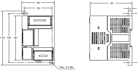
CPU Units with 14 or 20 I/O Points
CP1E-[]14/20D[][]-[]
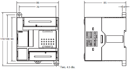
CP1E-[]14/20SD[][]-[]
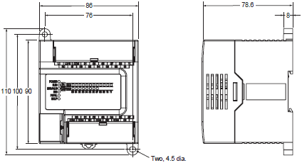
CPU Units with 30 I/O Points
CPU Units with 20 I/O Points and Built-in Analog
CP1E-[]30D[][]-[], CP1E-NA20D[]-[]
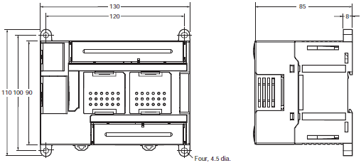
CP1E-[]30S(1)D[][]-[]
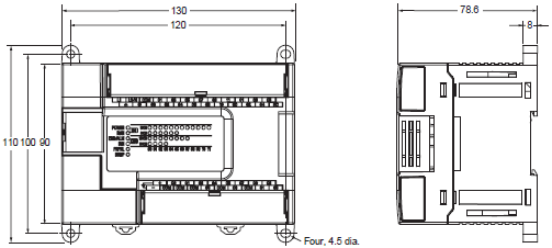
CPU Units with 40 I/O Points
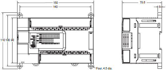
CP1E-[]40D[][]-[]
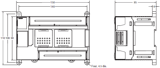
CP1E-[]40S(1)D[][]-[]
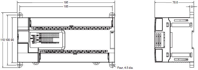
CPU Units with 60 I/O Points
CP1E-N60D[]-[]
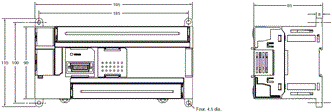
CP1E-[]60S(1)D[][]-[]
Expansion I/O Units and Expansion Units
CP1W-8E[][]/CP1W-SRT21
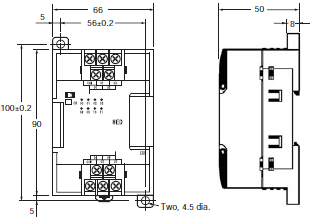
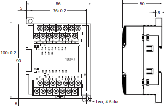
CP1W-20ED[]/CP1W-16E[][]/CP1W-AD04[]/CP1W-DA021/CP1W-DA04[]/CP1W-MAD[][]/ CP1W-TS[][]1/[][]2/[][]3
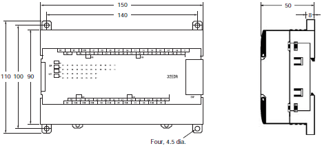
CP1W-40ED[]/CP1W-32E[][]/CP1W-TS004
last update: January 05, 2015
OMRON CP1E lineup
CP1E CP-series CP1E CPU Units/Lineuplast update: December 3, 2018
Applicable standards
Ask your OMRON representative for the most recent applicable standards for each model.
Basic Model
Renewal-type
E[][]S-type CP1E CPU Units (Built-in USB port)
| Product name | Specifications | External power supply (24 VDC) (A) | Current consump- tion (A) | Model | ||||||
|---|---|---|---|---|---|---|---|---|---|---|
| Power Supply | In- puts | Out- puts | Out- put type | Program capacity | Data memory capacity | 5 V | 24 V | |||
| E[][]S-type CPU Units with 14 I/O Points  | 100 to 240 VAC | 8 | 6 | Relay | 2K steps | 2K words | -- | 0.16 | 0.07 | CP1E-E14SDR-A |
| E[][]S-type CPU Units with 20 I/O Points  | 100 to 240 VAC | 12 | 8 | Relay | 2K steps | 2K words | -- | 0.17 | 0.08 | CP1E-E20SDR-A |
| E[][]S-type CPU Units with 30 I/O Points  | 100 to 240 VAC | 18 | 12 | Relay | 2K steps | 2K words | 0.30 | 0.17 | 0.07 | CP1E-E30SDR-A |
| E[][]S-type CPU Units with 40 I/O Points  | 100 to 240 VAC | 24 | 16 | Relay | 2K steps | 2K words | 0.30 | 0.17 | 0.09 | CP1E-E40SDR-A |
| E[][]S-type CPU Units with 60 I/O Points  | 100 to 240 VAC | 36 | 24 | Relay | 2K steps | 2K words | 0.30 | 0.17 | 0.13 | CP1E-E60SDR-A |
Normal-type
E[][]-type CP1E CPU Units (Built-in USB port)
| Product name | Specifications | External power supply (24 VDC) (A) | Current consump- tion (A) | Model | ||||||
|---|---|---|---|---|---|---|---|---|---|---|
| Power Supply | In- puts | Out- puts | Output type | Program capacity | Data memory capacity | 5 V | 24 V | |||
| E[][]-type CPU Units with 10 I/O Points  | 100 to 240 VAC | 6 | 4 | Relay | 2K steps | 2K words | --- | 0.08 | 0.04 | CP1E-E10DR-A |
| Transistor (sinking) | --- | 0.11 | --- | CP1E-E10DT-A | ||||||
| Transistor (sourcing) | --- | 0.11 | --- | CP1E-E10DT1-A | ||||||
| 24 VDC | Relay | --- | 0.08 | 0.04 | CP1E-E10DR-D | |||||
| Transistor (sinking) | --- | 0.11 | --- | CP1E-E10DT-D | ||||||
| Transistor (sourcing) | --- | 0.11 | --- | CP1E-E10DT1-D | ||||||
| E[][]-type CPU Units with 14 I/O Points  | 100 to 240 VAC | 8 | 6 | Relay | 2K steps | 2K words | --- | 0.16 | 0.07 | CP1E-E14DR-A |
| E[][]-type CPU Units with 20 I/O Points  | 100 to 240 VAC | 12 | 8 | Relay | 2K steps | 2K words | --- | 0.17 | 0.08 | CP1E-E20DR-A |
| E[][]-type CPU Units with 30 I/O Points  | 100 to 240 VAC | 18 | 12 | Relay | 2K steps | 2K words | 0.30 | 0.17 | 0.07 | CP1E-E30DR-A |
| E[][]-type CPU Units with 40 I/O Points  | 100 to 240 VAC | 24 | 16 | Relay | 2K steps | 2K words | 0.30 | 0.17 | 0.09 | CP1E-E40DR-A |
Application Model
Renewal-type
N[][]S1-type CP1E CPU Units (Built-in RS-232C, RS-485, USB ports)
| Product name | Specifications | Ex- ternal power supply (24 VDC) (A) | Current consump- tion (A) | Model | ||||||
|---|---|---|---|---|---|---|---|---|---|---|
| Power Supply | In- puts | Out- puts | Output type | Pro- gram ca- pacity | Data memory ca- pacity | 5 V | 24 V | |||
| N[][]S1-type CPU Units with 30 I/O Points  | 100 to 240 VAC | 18 | 12 | Relay | 8K steps | 8K words | 0.30 | 0.21 | 0.07 | CP1E-N30S1DR-A |
| DC24V | Transistor (sinking) | -- | 0.27 | 0.02 | CP1E-N30S1DT-D | |||||
| Transistor (sourcing) | -- | 0.27 | 0.02 | CP1E-N30S1DT1-D | ||||||
| N[][]S1-type CPU Units with 40 I/O Points  | 100 to 240 VAC | 24 | 16 | Relay | 8K steps | 8K words | 0.30 | 0.21 | 0.09 | CP1E-N40S1DR-A |
| DC24V | Transistor (sinking) | -- | 0.31 | 0.02 | CP1E-N40S1DT-D | |||||
| Transistor (sourcing) | -- | 0.31 | 0.02 | CP1E-N40S1DT1-D | ||||||
| N[][]S1-type CPU Units with 60 I/O Points  | 100 to 240 VAC | 36 | 24 | Relay | 8K steps | 8K words | 0.30 | 0.21 | 0.13 | CP1E-N60S1DR-A |
| DC24V | Transistor (sinking) | -- | 0.31 | 0.02 | CP1E-N60S1DT-D | |||||
| Transistor (sourcing) | -- | 0.31 | 0.02 | CP1E-N60S1DT1-D | ||||||
N[][]S-type CP1E CPU Units (Built-in RS-232C, USB ports)
| Product name | Specifications | Ex- ternal power supply (24 VDC) (A) | Current consump- tion (A) | Model | ||||||
|---|---|---|---|---|---|---|---|---|---|---|
| Power Supply | In- puts | Out- puts | Output type | Pro- gram ca- pacity | Data memory ca- pacity | 5 V | 24 V | |||
| N[][]S-type CPU Units with 30 I/O Points  | 100 to 240 VAC | 18 | 12 | Relay | 8K steps | 8K words | 0.30 | 0.21 | 0.07 | CP1E-N30SDR-A |
| DC24V | Transistor (sinking) | -- | 0.27 | 0.02 | CP1E-N30SDT-D | |||||
| Transistor (sourcing) | -- | 0.27 | 0.02 | CP1E-N30SDT1-D | ||||||
| N[][]S-type CPU Units with 40 I/O Points  | 100 to 240 VAC | 24 | 16 | Relay | 8K steps | 8K words | 0.30 | 0.21 | 0.09 | CP1E-N40SDR-A |
| DC24V | Transistor (sinking) | -- | 0.31 | 0.02 | CP1E-N40SDT-D | |||||
| Transistor (sourcing) | -- | 0.31 | 0.02 | CP1E-N40SDT1-D | ||||||
| N[][]S-type CPU Units with 60 I/O Points  | 100 to 240 VAC | 36 | 24 | Relay | 8K steps | 8K words | 0.30 | 0.21 | 0.13 | CP1E-N60SDR-A |
| DC24V | Transistor (sinking) | -- | 0.31 | 0.02 | CP1E-N60SDT-D | |||||
| Transistor (sourcing) | -- | 0.31 | 0.02 | CP1E-N60SDT1-D | ||||||
Normal-type
N/NA[][]-type CP1E CPU Units (Built-in RS-232C, USB ports)
| Product name | Specifications | Ex- ternal power supply (24 VDC) (A) | Current consump- tion (A) | Model | ||||||
|---|---|---|---|---|---|---|---|---|---|---|
| Power Sup- ply | Inputs | Out- puts | Output type | Pro- gram ca- pacity | Data mem- ory ca- pacity | 5 V | 24 V | |||
| N[][]-type CPU Units with 14 I/O Points  | 100 to 240 VAC | 8 | 6 | Relay | 8K steps | 8K words | --- | 0.17 | 0.07 | CP1E-N14DR-A |
| Transistor (sinking) | --- | 0.22 | 0.02 | CP1E-N14DT-A | ||||||
| Transistor (sourcing) | --- | 0.22 | 0.02 | CP1E-N14DT1-A | ||||||
| 24 VDC | Relay | --- | 0.17 | 0.07 | CP1E-N14DR-D | |||||
| Transistor (sinking) | --- | 0.22 | 0.02 | CP1E-N14DT-D | ||||||
| Transistor (sourcing) | --- | 0.22 | 0.02 | CP1E-N14DT1-D | ||||||
| N[][]-type CPU Units with 20 I/O Points  | 100 to 240 VAC | 12 | 8 | Relay | 8K steps | 8K words | --- | 0.18 | 0.08 | CP1E-N20DR-A |
| Transistor (sinking) | --- | 0.23 | 0.02 | CP1E-N20DT-A | ||||||
| Transistor (sourcing) | --- | 0.23 | 0.02 | CP1E-N20DT1-A | ||||||
| 24 VDC | Relay | --- | 0.18 | 0.08 | CP1E-N20DR-D | |||||
| Transistor (sinking) | --- | 0.23 | 0.02 | CP1E-N20DT-D | ||||||
| Transistor (sourcing) | --- | 0.23 | 0.02 | CP1E-N20DT1-D | ||||||
| N[][]-type CPU Units with 30 I/O Points  | 100 to 240 VAC | 18 | 12 | Relay | 8K steps | 8K words | 0.3 | 0.21 | 0.07 | CP1E-N30DR-A |
| Transistor (sinking) | 0.3 | 0.27 | 0.02 | CP1E-N30DT-A | ||||||
| Transistor (sourcing) | 0.3 | 0.27 | 0.02 | CP1E-N30DT1-A | ||||||
| 24 VDC | Relay | --- | 0.21 | 0.07 | CP1E-N30DR-D | |||||
| Transistor (sinking) | --- | 0.27 | 0.02 | CP1E-N30DT-D | ||||||
| Transistor (sourcing) | --- | 0.27 | 0.02 | CP1E-N30DT1-D | ||||||
| N[][]-type CPU Units with 40 I/O Points  | 100 to 240 VAC | 24 | 16 | Relay | 8K steps | 8K words | 0.3 | 0.21 | 0.09 | CP1E-N40DR-A |
| Transistor (sinking) | 0.3 | 0.31 | 0.02 | CP1E-N40DT-A | ||||||
| Transistor (sourcing) | 0.3 | 0.31 | 0.02 | CP1E-N40DT1-A | ||||||
| 24 VDC | Relay | --- | 0.21 | 0.09 | CP1E-N40DR-D | |||||
| Transistor (sinking) | --- | 0.31 | 0.02 | CP1E-N40DT-D | ||||||
| Transistor (sourcing) | --- | 0.31 | 0.02 | CP1E-N40DT1-D | ||||||
| N[][]-type CPU Units with 60 I/O Points  | 100 to 240 VAC | 36 | 24 | Relay | 8K steps | 8K words | 0.3 | 0.21 | 0.13 | CP1E-N60DR-A |
| Transistor (sinking) | 0.3 | 0.31 | 0.02 | CP1E-N60DT-A | ||||||
| Transistor (sourcing) | 0.3 | 0.31 | 0.02 | CP1E-N60DT1-A | ||||||
| 24 VDC | Relay | --- | 0.21 | 0.13 | CP1E-N60DR-D | |||||
| Transistor (sinking) | --- | 0.31 | 0.02 | CP1E-N60DT-D | ||||||
| Transistor (sourcing) | --- | 0.31 | 0.02 | CP1E-N60DT1-D | ||||||
| NA-type CPU Units with 20 I/O Points (Built-in analog)  | 100 to 240 VAC | 12 (Built-in analog inputs: 2) | 8 (Built-in analog outputs: 1) | Relay | 8K steps | 8K words | 0.3 | 0.18 | 0.11 | CP1E-NA20DR-A |
| 24 VDC | Transistor (sinking) | --- | 0.23 | 0.09 | CP1E-NA20DT-D | |||||
| Transistor (sourcing) | --- | 0.23 | 0.09 | CP1E-NA20DT1-D | ||||||
Optional Products
Battery Set
| Product name | Specifications | Model |
|---|---|---|
Battery Set | For N/NA[][](S[])-type CP1E CPU Units Note: Mount a Battery to an N/NA[][](S[])-type CPU Unit if the data in the following areas must be backed up for power interruptions. • DM Area (D) (except backed up words in the DM Area), Holding Area (H), Counter Completion Flags (C), Counter Present Values (C), Auxiliary Area (A), and Clock Function (Use batteries within two years of manufacture.) | CP1W-BAT01 |
Option Board (for CP1E N30/40/60 or NA20 CPU Units)
The Options cannot be used for CP1E N14/20, N30/40/60S(1), E10/14/20/30/40/60(S) CPU Units.
| Product name | Specifications | Model | |
|---|---|---|---|
| RS-232C Option Board |  | One RS-232C Option Board can be mounted to the Option Board slot. | CP1W-CIF01 |
| RS-422A/485 Option Board |  | One RS-422A/485 Option Board can be mounted to the Option Board slot. | CP1W-CIF11 |
| RS-422A/485 Isolated-type Option Board |  | CP1W-CIF12-V1 | |
| Ethernet Option Board |  | One Ethernet Option Board can be mounted to the Option Board slot. CP1E CPU Units are supported by CP1W-CIF41 version 2.0 or higher. When using CP1W-CIF41, CX-Programmer version 9.12 or higher is required. | CP1W-CIF41 |
| Analog Input Option Board |  | Can be mounted in CPU Unit Option Board slot. 2 analog inputs. 0-10V (Resolution:1/4000), 0-20mA (Resolution: 1/2000). | CP1W-ADB21 * |
| Analog Output Option Board |  | Can be mounted in CPU Unit Option Board slot. 2 analog outputs. 0-10V (Resolution:1/4000). | CP1W-DAB21V * |
| Analog I/O Option Board |  | Can be mounted in CPU Unit Option Board slot. 2 analog inputs. 0-10V (Resolution:1/4000), 0-20mA (Resolution:1/2000). 2 analog outputs. 0-10V (Resolution:1/4000). | CP1W-MAB221 * |
Note: It is not possible to use a CP-series Ethernet Option Board version 1.0 (CP1W-CIF41), LCD Option Board (CP1W-
DAM01), or Memory Card (CP1W-ME05M) with a CP1E CPU Unit.
* Support is provided with CP1E CPU Unit version 1.2 and later.
Expansion I/O Units and Expansion Units (for CP1E E30/40/60(S), N30/40/60(S[]), or NA20 CPU Units)
CP1E E10/14/20(S) or N14/20 CPU Units do not support Expansion I/O Units and Expansion Units.
| Unit type | Product name | Specifications | Current consumption (A) | Model | ||||
|---|---|---|---|---|---|---|---|---|
| Inputs | Out- puts | Output type | 5 V | 24 V | ||||
| CP1W Expan- sion I/O Units | Input Unit | 8 | --- | 24 VDC Input | 0.018 | -- | CP1W-8ED | |
Output Units | --- | 8 | Relay | 0.026 | 0.044 | CP1W-8ER | ||
| Transistor (sinking) | 0.075 | -- | CP1W-8ET | |||||
| Transistor (sourcing) | 0.075 | -- | CP1W-8ET1 | |||||
Output Units | --- | 16 | Relay | 0.042 | 0.090 | CP1W-16ER | ||
| Transistor (sinking) | 0.076 | -- | CP1W-16ET | |||||
| Transistor (sourcing) | 0.076 | -- | CP1W-16ET1 | |||||
Output Units | --- | 32 | Relay | 0.049 | 0.131 | CP1W-32ER | ||
| Transistor (sinking) | 0.113 | -- | CP1W-32ET | |||||
| Transistor (sourcing) | 0.113 | -- | CP1W-32ET1 | |||||
I/O Units | 12 | 8 | Relay | 0.103 | 0.044 | CP1W-20EDR1 | ||
| Transistor (sinking) | 0.130 | -- | CP1W-20EDT | |||||
| Transistor (sourcing) | 0.130 | -- | CP1W-20EDT1 | |||||
I/O Units | 24 | 16 | Relay | 0.080 | 0.090 | CP1W-40EDR | ||
| Transistor (sinking) | 0.160 | -- | CP1W-40EDT | |||||
| Transistor (sourcing) | 0.160 | -- | CP1W-40EDT1 | |||||
| CP1W Expan- sion Units | Analog Input Unit  | 4CH | -- | Input range: 0 to 5 V, 1 to 5 V, 0 to 10 V, ±10 V, 0 to 20 mA, or 4 to 20 mA. | Resolution: 1/6000 | 0.100 | 0.090 | CP1W-AD041 |
| Resolution: 1/12000 | 0.100 | 0.050 | CP1W-AD042 | |||||
| Analog Output Unit  | -- | 2CH | Output range: 1 to 5 V, 0 to 10 V, ±10 V, 0 to 20 mA, or 4 to 20 mA. | Resolution: 1/6000 | 0.040 | 0.095 | CP1W-DA021 | |
| -- | 4CH | Resolution: 1/6000 | 0.080 | 0.124 | CP1W-DA041 | |||
| Resolution: 1/12000 | 0.070 | 0.160 | CP1W-DA042 | |||||
| Analog I/O Unit  | 4CH | 4CH | Input range: 0 to 5 V, 1 to 5 V, 0 to 10 V, ±10 V, 0 to 20 mA, or 4 to 20 mA. Output range: 1 to 5 V, 0 to 10 V, ±10 V, 0 to 20 mA, or 4 to 20 mA. | Resolution: 1/12000 | 0.120 | 0.170 | CP1W-MAD44 | |
| 4CH | 2CH | Resolution: 1/12000 | 0.120 | 0.120 | CP1W-MAD42 | |||
| 2CH | 1CH | Resolution: 1/6000 | 0.083 | 0.110 | CP1W-MAD11 | |||
| Temperature Sensor Unit  | 2CH | -- | Sensor type: Thermocouple (J or K) | 0.040 | 0.059 | CP1W-TS001 | ||
| 4CH | -- | Sensor type: Thermocouple (J or K) | 0.040 | 0.059 | CP1W-TS002 | |||
| 2CH | -- | Sensor type: Platinum resistance thermometer (Pt100 or JPt100) | 0.054 | 0.073 | CP1W-TS101 | |||
| 4CH | -- | Sensor type: Platinum resistance thermometer (Pt100 or JPt100) | 0.054 | 0.073 | CP1W-TS102 | |||
| 4CH | -- | Sensor type: Thermocouple (J or K) 2channels can be used as analog input. Input range: 1 to 5 V, 0 to 10 V, 4-20 mA | Resolution: 1/12000 | 0.070 | 0.030 | CP1W-TS003 | ||
| 12CH | -- | Sensor type: Thermocouple (J or K) | 0.080 | 0.050 | CP1W-TS004 | |||
| CompoBus/S I/O Link Unit  | 8 | 8 | CompoBus/S slave | 0.029 | -- | CP1W-SRT21 | ||
I/O Connecting Cable
| Product name | Specifications | Model |
|---|---|---|
| I/O Connecting Cable | 80 cm (for CP1W Expansion I/O Units and Expansion Units) Only one I/O Connecting Cable can be used in each PLC. | CP1W-CN811 |
Note: An I/O Connecting Cable (approx. 6 cm) for horizontal connection is provided with CP1W Expansion I/O Units and
Expansion Units.
DIN Track Accessories
| Name | Specifications | Model | |
|---|---|---|---|
| DIN Track | Length: 0.5 m; Height: 7.3 mm | PFP-50N | |
| Length: 1 m; Height: 7.3 mm | PFP-100N | ||
| Length: 1 m; Height: 16 mm | PFP-100N2 | ||
| End Plate | A stopper to secure the Units on the DIN Track. | PFP-M | |
Programming Devices
Software
| Product name | Specifications | Model | ||
|---|---|---|---|---|
| Number of licenses | Media | |||
| FA Integrated Tool Package CX-One Lite Ver.4.[] | CX-One Lite is a subset of the complete CX-One package that provides only the Support Software required for micro PLC applications. CX-One Lite runs on the following OS. OS: Windows XP (Service Pack 3 or higher, 32-bit version)/Windows Vista (32-bit/64-bit version)/Windows 7 (32-bit/64-bit version)/Windows 8 (32-bit/64-bit version)/Windows 8.1 (32-bit/64-bit version)/Windows 10 (32-bit/64-bit version) CX-One Lite Ver. 4.[] includes Micro PLC Edition CX- Programmer Ver.9.[]. | 1 license | DVD | CXONE-LT01D-V4 |
| FA Integrated Tool Package CX-One Package Ver. 4.[] | CX-One is a comprehensive software package that integrates Support Software for OMRON PLCs and components. CX-One runs on the following OS. OS: Windows XP (Service Pack 3 or higher, 32-bit version)/Windows Vista (32-bit/64-bit version)/Windows 7 (32-bit/64-bit version)/Windows 8 (32-bit/64-bit version)/Windows 8.1 (32-bit/64-bit version)/Windows 10 (32-bit/64-bit version) CX-One Ver. 4.[] includes CX-Programmer Ver. 9.[]. | 1 license * | DVD | CXONE-AL01D-V4 |
Note: 1. The E20/30/40(S), N20/N30/N40(S) CPU Units are supported by CX-Programmer version 8.2 or higher.
The E10, E14, N14, N60, and NA20 CPU Units are supported by CX-Programmer version 9.03 or higher. When
Micro PLC Edition CXProgrammer is used, you need version 9.03 or higher.
The E60S CPU Units are supported by CX-Programmer version 9.42 or higher. When Micro PLC Edition CX-
Programmer is used, you need version 9.42 or higher.
2. The CX-One and CX-One Lite cannot be simultaneously installed on the same computer.
* Multi licenses (3, 10, 30, or 50 licenses) and DVD media without licenses are also available for the CX-One.
The following tables lists the Support Software that can be installed from CX-One
| Support Software in CX-One | CX-One Lite Ver.4.[] | CX-One Ver.4.[] | |
|---|---|---|---|
| Micro PLC Edition CX-Programmer | Ver.9.[] | Yes | No |
| CX-Programmer | Ver.9.[] | No | Yes |
| CX-Integrator | Ver.2.[] | Yes | Yes |
| Switch Box Utility | Ver.1.[] | Yes | Yes |
| CX-Protocol | Ver.1.[] | No | Yes |
| CX-Simulator | Ver.1.[] | Yes | Yes |
| CX-Position | Ver.2.[] | No | Yes |
| CX-Motion-NCF | Ver.1.[] | No | Yes |
| CX-Motion-MCH | Ver.2.[] | No | Yes |
| CX-Motion | Ver.2.[] | No | Yes |
| CX-Drive | Ver.1.[] | Yes | Yes |
| CX-Process Tool | Ver.5.[] | No | Yes |
| Faceplate Auto-Builder for NS | Ver.3.[] | No | Yes |
| CX-Designer | Ver.3.[] | Yes | Yes |
| NV-Designer | Ver.1.[] | Yes | Yes |
| CX-Thermo | Ver.4.[] | Yes | Yes |
| CX-ConfiguratorFDT | Ver.1.[] | Yes | Yes |
| CX-FLnet | Ver.1.[] | No | Yes |
| Network Configurator | Ver.3.[] | Yes | Yes |
| CX-Server | Ver.4.[] | Yes | Yes |
Note: For details, refer to the CX-One Catalog (Cat. No. R134).
last update: December 3, 2018
OMRON CP1E catalog
CP1E CP-series CP1E CPU Units/Catalog- Catalog
- Manual
- CAD
English
Global Edition
| Catalog Name | Catalog Number [size] | Last Update | |
|---|---|---|---|
| | P061-E1-10 [7647KB] | Jan 07, 201920190107 | CP1E Data Sheet |
| | P060-E1-11 [4858KB] | Jan 05, 201820180105 | CP1E Catalog |
| | P082-E1-05 [5577KB] | Jan 05, 201820180105 | CP1 Catalog |
| | P090-E1-07 [18214KB] | Aug 20, 201820180820 | FA Controller Catalog |
OMRON CP1E specification
CP1E CP-series CP1E CPU Units/Specificationslast update: January 5, 2018
General Specifications
| Type | AC power supply models | DC power supply models | |
|---|---|---|---|
| Model | CP1E-[][][]S[]D[]-A CP1E-[][][]D[]-A | CP1E-[][][]S[]D[]-D CP1E-[][][]D[]-D | |
| Enclosure | Mounted in a panel | ||
| Dimensions (H × D × W) | E/N/NA[][]-type CPU Unit with 10 I/O points (CP1E-E10D[]-[]): 90mm *1 × 85mm *2 × 66 mm CPU Unit with 14 or 20 I/O points (CP1E-[]14D[]-[]/[]20D[]-[]): 90mm *1 × 85mm *2 × 86 mm CPU Unit with 30 I/O points (CP1E-[]30D[]-[]): 90mm *1 × 85mm *2 × 130 mm CPU Unit with 40 I/O points (CP1E-[]40D[]-[]): 90mm *1 × 85mm *2 × 150 mm CPU Unit with 60 I/O points (CP1E-N60D[]-[]): 90mm *1 × 85mm *2 × 195 mm CPU Unit with 20 I/O points and built-in analog (CP1E-NA20D[]-[]): 90mm *1 × 85mm *2 × 130 mm E/N/[][]S(1)-type CPU Unit with 14 or 20 I/O points (CP1E-[]14SD[]-[]/[]20SD[]-[]): 90mm *1 × 79mm *2 × 86 mm CPU Unit with 30 I/O points (CP1E-[]30S(1)D[]-[]): 90mm *1 × 79mm *2 × 130 mm CPU Unit with 40 I/O points (CP1E-[]40S(1)D[]-[]): 90mm *1 × 79mm *2 × 150 mm CPU Unit with 60 I/O points (CP1E-[]60S(1)D[]-[]): 90mm *1 × 79mm *2 × 195 mm | ||
| Weight | CPU Unit with 10 I/O points (CP1E-E10D[]-[]): 300g max. CPU Unit with 14 I/O points (CP1E-[]14(S)D[]-[]): 360g max. CPU Unit with 20 I/O points (CP1E-[]20(S)D[]-[]): 370g max. CPU Unit with 30 I/O points (CP1E-[]30(S[])D[]-[]): 600g max. CPU Unit with 40 I/O points (CP1E-[]40(S[])D[]-[]): 660g max. CPU Unit with 60 I/O points (CP1E-[]60(S[])D[]-[]): 850g max. CPU Unit with 20 I/O points and built-in analog (CP1E-NA20D[]-[]): 680g max. | ||
| Elec- trical spec- ifica- tions | Supply voltage | 100 to 240 VAC 50/60 Hz | 24 VDC |
| Operating voltage range | 85 to 264 VAC | 20.4 to 26.4 VDC | |
| Power consumption | 15 VA/100 VAC max. 25 VA/240 VAC max. (CP1E-E10D[]-A/[]14(S)D[]-A/ []20(S)D[]-A) | 9 W max. (CP1E-E10D[]-D) 13 W max. (CP1E-N14D[]-D/N20D[]-D) | |
| 50 VA/100 VAC max. 70 VA/240 VAC max. (CP1E-NA20D[]-A/[]30(S[])D[]-A/ []40(S[])D[]-A/N60(S[])D[]-A) | 20 W max. (CP1E-NA20D[]-D/N30(S[])D[]-D/ N40(S[])D[]-D/N60(S[])D[]-D) *4 | ||
| Inrush current | 120 VAC, 20 A for 8 ms max. for cold start at room temperature 240 VAC, 40 A for 8 ms max. for cold start at room temperature | 24 VDC, 30 A for 20 ms max. for cold start at room temperature | |
| External power supply *3 | Not provided. (CP1E-E10D[]-A/[]14(S)D[]-A/ []20(S)D[]-A) 24 VDC, 300 mA (CP1E-NA20D[]-A/[]30D[]-A/ []40D[]-A/[]60D[]-A/[]30SDR-A/ []40SDR-A/[]60SDR-A) | Not provided | |
| Insulation resistance | 20 MΩ min. (at 500 VDC) between the external AC terminals and GR terminals | Except between DC primary current and DC secondary current | |
| Dielectric strength | 2,300 VAC 50/60Hz for 1 min between AC external and GR terminals Leakage current: 5 mA max. | Except between DC primary current and DC secondary current | |
| Power OFF detection time | 10 ms min. | 2 ms min. | |
| Appli- cation envi- ron- ment | Ambient operating temperature | 0 to 55 °C | |
| Ambient humidity | 10% to 90% | ||
| Atmosphere | No corrosive gas. | ||
| Ambient storage temperature | -20 to 75 °C (excluding battery) | ||
| Altitude | 2,000 m max. | ||
| Pollution degree | 2 or less: Conforms to JIS B3502 and IEC 61131-2. | ||
| Noise resistance | 2 kV on power supply line (Conforms to IEC61000-4-4.) | ||
| Overvoltage category | Category II: Conforms to JIS B3502 and IEC 61131-2. | ||
| EMC Immunity Level | Zone B | ||
| Vibration resistance | Conforms to JIS 60068-2-6. 5 to 8.4 Hz with 3.5-mm amplitude, 8.4 to 150 Hz Acceleration of 9.8 m/s2 for 100 min in X, Y, and Z directions (10 sweeps of 10 min each = 100 min total) | ||
| Shock resistance | Conforms to JIS 60068-2-27. 147 m/s2, 3 times in X, Y, and Z directions | ||
| Terminal block | Fixed (not removable) | ||
| Terminal screw size | M3 | ||
| Applicable standards | Conforms to EC Directive | ||
| Grounding method | Ground to 100 Ω or less. | ||
* 1 Total of 110 mm with mounting brackets.
* 2 Excluding cables.
* 3 Use the external power supply to power input devices. Do not use it to drive output devices.
* 4 This is the rated value for the maximum system configuration. Use the following formula to calculate power
consumption for CPU Units with DC power.
Formula: DC power consumption = (5 V current consumption ✕ 5 V/70% (internal power efficiency) + 24V current
consumption) ✕ 1.1 (current fluctuation factor)
The above calculation results show that a DC power supply with a greater capacity is required.
Performance Specifications
| Item | CP1E-E[][]SD[]-[] CP1E-[][]D[]-[] | CP1E-N[][]S[]D[]-[] CP1E-N[][]D[]-[] CP1E-NA[][]D[]-[] | ||
|---|---|---|---|---|
| Program capacity | 2 K steps (8 Kbytes) including the symbol table, comments, and program indices of the CX-Programmer | 8 K steps (32 Kbytes) including the symbol table, comments, and program indices of the CX-Programmer | ||
| Control method | Stored program method | |||
| I/O control method | Cyclic scan with immediate refreshing | |||
| Program language | Ladder diagram | |||
| Instructions | Approximately 200 | |||
| Proc- essing speed | Overhead processing time | 0.4 ms | ||
| Instruction execution times | Basic instructions (LD): 1.19 µs min. Special instructions (MOV): 7.9 µs min. | |||
| Number of CP1W-series Expansion Units connected | CP1E-E10D[]-[]/[]14(S)D[]-[]/[]20(S)D[]-[]: None CP1E-[]30(S[])D[]-[]/[]40(S[])D[]-[]/[]60(S[])D[]-[]/NA20(S[])D[]-[]: 3 units | |||
| Maximum number of I/O points | CP1E-E10D[]-[]: 10 CP1E-[]14(S)D[]-[]: 14 CP1E-[]20(S)D[]-[]: 20 CP1E-[]30(S[])D[]-[]: 150 (30 built in, 40 × 3 expansion) CP1E-[]40(S[])D[]-[]: 160 (40 built in, 40 × 3 expansion) CP1E-[]60(S[])D[]-[]: 180 (60 built in, 40 × 3 expansion) CP1E-NA20D[]-[]: 140 (20 built in, 40 × 3 expansion) | |||
| Built-in I/O | CP1E-E10D[]-[]: 10 (6 inputs, 4 outputs) CP1E-[]14(S)D[]-[]: 14 (8 inputs, 6 outputs) CP1E-[]20(S)D[]-[]: 20 (12 inputs, 8 outputs) CP1E-[]30(S[])D[]-[]: 30 (18 inputs, 12 outputs) CP1E-[]40(S[])D[]-[]: 40 (24 inputs, 16 outputs) CP1E-[]60(S[])D[]-[]: 60 (36 inputs, 24 outputs) CP1E-NA20D[]-[]: 20 (12 inputs, 8 outputs) | |||
| Built-in input func- tions | High- speed counters | High-speed counter mode/ maximum frequency | Incremental Pulse Inputs 10 kHz: 6 counters 5 counters (only for 10 I/O points) Up/Down Inputs 10 kHz: 2 counters Pulse + Direction Inputs 10 kHz: 2 counters Differential Phase Inputs (4x) 5 kHz: 2 counters | Incremental Pulse Inputs 100 kHz: 2 counters, 10 kHz: 4 counters Up/Down Inputs 100 kHz: 1 counters, 10 kHz: 1 counters Pulse + Direction Inputs 100 kHz: 2 counters Differential Phase Inputs (4x) 50 kHz: 1 counter, 5 kHz: 1 counter |
| Counting mode | Linear mode Ring mode | |||
| Count value | 32 bits | |||
| Counter reset modes | Phase Z and software reset (excluding increment pulse input) Software reset | |||
| Control method | Target Matching Range Comparison | |||
| Input interrupts | 6 inputs (4 inputs only for 10 I/O points) Interrupt input pulse width: 50 µs min. | |||
| Quick-response Inputs | 6 inputs (4 inputs only for 10 I/O points) Input pulse width: 50 µs min. | |||
| Normal input | Input constants | Delays can be set in the PLC Setup (0 to 32 ms, default: 8 ms). Set values: 0, 1, 2, 4, 8, 16, or 32 ms | ||
| Built-in output func- tions | Pulse outputs (Models with transistor outputs only) | Pulse output method and output frequency | Pulse output function not included | Pulse + Direction Mode 1 Hz to 100 kHz: 2 outputs |
| Output mode | Continuous mode (for speed control) Independent mode (for position control) | |||
| Number of output pulses | elative coordinates: 0000 0000 to 7FFF FFFF hex (0 to 2147483647) Absolute coordinates: 8000 0000 to 7FFF FFFF hex (-2147483647 to 2147483647) | |||
| Acceleration/ deceleration curves | Trapezoidal acceleration and deceleration (Cannot perform S-curve acceleration and deceleration.) | |||
| Changing SVs during instruction execution | Only target position can be changed. | |||
| Origin searches | Included | |||
| Pulse outputs (Models with transistor outputs only) | Frequency | PWM output function not included | 2.0 to 6,553.5 Hz (in increments of 0.1 Hz) with 1 output or 2 Hz to 32,000 Hz (in increments of 1 Hz) with 1 output | |
| Duty factor | 0.0% to 100.0% (in increments of 0.1%) Accuracy: +1%/-0% at 2 Hz to 10,000 Hz and +5%/-0% at 10,000 Hz to 32,000 kHz | |||
| Output mode | Continuous Mode | |||
| Built-in analog | Analog input | Analog function not included | Setting range: 0 to 6,000 (2 channels only for NA-type) | |
| Analog output | Setting range: 0 to 6,000 (1 channels only for NA-type) | |||
| Analog adjusters | E/N/NA[][]-type: 2 adjusters (Setting range: 0 to 255) E/N[][]S(1)-type: None | |||
| Com- muni- cations | B-type Peripheral USB Port | Conforming to USB 2.0 B type connector | ||
| Transmission distance | 5 m max. | |||
| Built-in RS-232C port | No built-in RS-232C port | Interface: Conforms to EIA RS-232C. | ||
| Communications method | Half duplex | |||
| synchronization | Start-stop | |||
| Baud rate | 1.2, 2.4, 4.8, 9.6, 19.2, 38.4, 57.6, or 115.2 kbps | |||
| Transmission distance | 15 m max. | |||
| Supported protocol | • Host Link • 1:N NT Link • No-protocol mode • Serial PLC Links (master, slave) • Modbus-RTU Easy Master | |||
| Built-in RS-485 port | No built-in RS-485 port | N30/40/60S1-type only Interface: Conforms to EIA RS-485. 2-wire sensors No isolation | ||
| Communications method | Half duplex | |||
| synchronization | Start-stop | |||
| Baud rate | 1.2, 2.4, 4.8, 9.6, 19.2, 38.4, 57.6, or 115.2 kbps | |||
| Transmission distance | 50 m max. | |||
| Supported protocol | • Host Link • 1:N NT Link • No-protocol mode • Serial PLC Links (master, slave) • Modbus-RTU Easy Master | |||
| Serial Option port | Option Board cannot be mounted. | N30/40/60 and NA20-type only 1 port | ||
| Mountable Option Boards | One RS-232C port: CP1W-CIF01 One RS-422A/485 port (not isolated): CP1W-CIF11 One RS-422A/485 port (isolated): CP1W-CIF12-V1 One Ethernet port: CP1W-CIF41 | |||
| Communications method | Depends on Option Board. | |||
| synchronization | Depends on Option Board. | |||
| Baud rate | 1.2, 2.4, 4.8, 9.6, 19.2, 38.4, 57.6, or 115.2 kbps | |||
| Compatible protocols | • Host Link • 1:N NT Link • No-protocol mode • Serial PLC Links (master, slave) • Modbus-RTU Easy Master | |||
| Number of tasks | 17 • One cyclic execution task • One scheduled interrupt task (always interrupt task 1) • Six input interrupt tasks (interrupt tasks 2 to 7) • Sixteen high-speed counter interrupt tasks (interrupt tasks 1 to 16) | |||
| Maximum subroutine number | 128 | |||
| Maximum jump number | 128 | |||
| Scheduled interrupt tasks | 1 interrupt task | |||
| Clock | Clock function not included. The time of error occurrence displays 01-01-01 01:01:01 Sunday | Included. Accuracy (monthly deviation): -4.5 min to -0.5 min at ambient temperature of 55°C, -2.0 min to +2.0 min at ambient temperature of 25°C, -2.5 min to +1.5 min at ambient temperature of 0°C | ||
| Memory backup | Built-in EEPROM | Ladder programs and parameters are automatically saved to built-in EEPROM A section of the Data Memory Area can be saved to the built-in EEPROM. | ||
| Battery backup With CP1W-BAT01 Battery (Sold separately) | Battery cannot be mounted. | CP1W-BAT01 can be used. Maximum battery service life: 5 years Backup Time Guaranteed value (ambient temperature: 55°C): 13,000 hours (approx. 1.5 years) Effective value (ambient temperature: 25°C): 43,000 hours (approx. 5 years) | ||
| CIO Area | Input Bits | 1,600 bits (100 words): CIO 0.00 to CIO 99.15 (CIO 00 to CIO 99) | ||
| Output Bits | 1,600 bits (100 words): CIO 100.00 to CIO 199.15 (CIO 100 to CIO 199) | |||
| Serial PLC Link Words | 1,440 bits (90 words): CIO 200.00 to CIO 289.15 (words CIO 200 to CIO 289) | |||
| Work Area (W) | 1,600 bits (100 words): W0.00 to W99.15 (W0 to W99) | |||
| Holding Area (H) | 800 bits (50 words): H0.00 to H49.15 (H0 to H49) Bits in this area maintain their ON/OFF status when operating mode is changed. | |||
| Auxiliary Area (A) | Read-only: 7,168 bits (448 words) A0 to A447 Read/write: 4,896 bits (306 words) in words A448 to A753 | |||
| Temporary Relay Area (TR) (TR Area) | 16 bits: TR0 to TR15 | |||
| Timer Area (T) | 256 timer numbers (T0 to T255 (separate from counters)) | |||
| Counter Area (C) | 256 counter numbers (C0 to C255 (separate from timers)) | |||
| Data Memory Area (D) | 2 Kwords: D0 to D2047 Of these, 1,500 words can be saved to the backup memory (built-in EEPROM) using settings in the Auxiliary Area. | 8 Kwords: D0 to D8191 Of these, 7,000 words can be saved to the backup memory (built-in EEP-ROM) using settings in the Auxiliary Area | ||
| Operating modes | PROGRAM mode: Program execution is stopped. Preparations can be executed prior to program execution in this mode. MONITOR mode: Programs are executed. Some operations, such as online editing, and changes to present values in I/O memory, are enabled in this mode. RUN mode: Programs are executed. This is the normal operating mode. | |||
last update: January 5, 2018
- NO. CP1E
- TYPE:Programmable Controllers CP1
 Copyright Statement
 - DATE:2021-06-10
- Associated products:
CJ2M-CPU3[] / CPU1[] / MD21[] CJ-series CJ2M CPU Units, Pulse I/O Modules/Features CP1L CP series CP1L CPU Unit/Features