
OMRON XW2R (PLCs)Power Supplies / In Addition/ Wiring Systems/Connector-Terminal Block Conversion Units
OMRON XW2R (PLCs) Power Supplies / In Addition
- XW2R (PLCs) Connector-Terminal Block Conversion Units for PLCs/Catalog
- XW2R (PLCs) Connector-Terminal Block Conversion Units for PLCs/Specifications
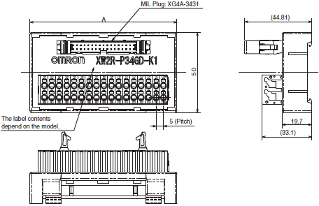
- XW2R (PLCs) Connector-Terminal Block Conversion Units for PLCs/Dimensions
- XW2R (PLCs) Connector-Terminal Block Conversion Units for PLCs/Lineup
- Purchase the OMRON XW2R (PLCs) Connector-Terminal Block Conversion Units
OMRON XW2R (PLCs) Dimensions
/Images/l_3153-25-146875-198x198.jpglast update: May 8, 2017
• Wiring patterns that are specifically designed for PLCs reduce the work required to check signal layout.
• Terminal block signal labels give the PLC addresses.
• Models available with Phillips screw, slotted screw, push-in, or e-CON connections.
• Models available with and without power supply terminals.
• Mounting to DIN Track is possible.
last update: May 8, 2017
Purchase the OMRON Connector-Terminal Block Conversion Units Please fill in the following
If you have just landed here, this product OMRON XW2R (PLCs) Power Supplies / In Addition,Power Supplies / In Addition is offered online by Tianin FLD Technical Co.,Ltd. This is an online store providing Power Supplies / In Addition at wholesale prices for consumers. You can call us or send enquiry, we would give you the prices, packing,deliverty and more detailed information on the XW2R (PLCs) We cooperate with DHL,TNT,FEDEX,UPS,EMS,etc.They guarantee to meet your needs in terms of time and money,even if you need your OMRON XW2R (PLCs)Power Supplies / In Addition tomorrow morning (aka overnight or next day air) on your desk, 2, 3 days or more.Note to international customers, YES, we ship worldwide.
NB-S Series Programmable Terminal/Features
NJ501-1[]20 / NJ101-[][]20 NJ-series Database Connection CPU Units/Features
EE-SPY31 / 41 Light Convergent Reflective Photomicrosensor/Features
F3SG-R Series Safety Light Curtain/Features
XS5 NEXT Series Round Oil-resistant Connectors (M12 Smartclick)/Features
OMRON XW2R (PLCs) catalog
XW2R (PLCs) Connector-Terminal Block Conversion Units for PLCs/Catalog- Catalog
- CAD
English
Global Edition
| Catalog Name | Catalog Number [size] | Last Update | |
|---|---|---|---|
| | - [11993KB] | Apr 02, 201820180402 | XW2R (PLCs) Data Sheet |
| | G077-E1-03 [21666KB] | Apr 02, 201820180402 | XW2R Series Catalog |
| | G129-E1-02 [950KB] | Jun 01, 201820180601 | XW2 Series Table of Connector-Terminal Block Conversion Units and connectable device combinations |
OMRON XW2R (PLCs) specification
XW2R (PLCs) Connector-Terminal Block Conversion Units for PLCs/Specificationslast update: April 01, 2015
Models for Connection to OMRON PLCs
with power supply terminals
Push-in spring
| Rated current | 16 Points: 1 A/signal, 4 A/common 32 Points: 1 A/signal, 8 A/common | |
|---|---|---|
| Rated voltage | 24 VDC | |
| Insuration resistance | 100 MΩ min. (at 500 VDC) | |
| Dielectric strength | 500 VAC for 1 ferrulemin (leakage current: 1 mA max.) | |
| Ambient operating temperature | 0 to 55°C | |
| Applicable wires | Applicable wire sizes | AWG 24 to 14 (ferrules) AWG 28 to 14 (stranded or solid) (Outer diameter of insulation must be 4 mm max) |
| Stripped length | AWG 28-16: 8 to 10 mm AWG 14: 9 to 10 mm | |
e-CON Type
| Rated current | Power supply terminal block: 4 A/16 poles or 8 A/32 poles | |
|---|---|---|
| Connectors/e-CON Connectors: 1 A (However, rated current of e-CON Connector depends on the wires that are used.) | ||
| Rated voltage | 24 VDC | |
| Insuration resistance | 100 MΩ min. (at 500 VDC) | |
| Dielectric strength | 500 VAC for 1 min (leakage current: 1 mA max.) | |
| Ambient operating temperature | 0 to 55°C | |
| Applicable wires | Applicable wire sizes | AWG 24 to 14 (ferrules) AWG 28 to 14 (stranded wires) AWG 28 to 16 (solid wires) * (Outer diameter of insulation must be 4 mm max) |
| Stripped length | AWG 28-16: 8 to 10 mm AWG 14: 9 to 10 mm | |
* This is the applicable range for the power supply terminal block. For the applicable wire sizes for I/O Connectors (e-
CON), refer to "Input Device Connectors: XN2 e-CON Connectors".
without power supply terminals
Phillips screw
| Rated current | 0.5 A/signal, 4 A/common | |
|---|---|---|
| Rated voltage | 24 VDC | |
| Insuration resistance | 100 MΩ min. (at 500 VDC) | |
| Dielectric strength | 500 VAC for 1 min (leakage current: 1 mA max.) | |
| Ambient operating temperature | 0 to 55°C | |
| Applicable wires | Applicable wire sizes | AWG 22 to 16 (round or forked crimp terminals) AWG 26 to 16 (stranded or solid wires) |
| Stripped length | 9 mm | |
| Tightening | 0.5 Nm | |
Slotted screw (rise up)
| Rated current | 0.5 A/signal, 4 A/common | |
|---|---|---|
| Rated voltage | 24 VDC | |
| Insuration resistance | 100 MΩ min. (at 500 VDC) | |
| Dielectric strength | 500 VAC for 1 min (leakage current: 1 mA max.) | |
| Ambient operating temperature | 0 to 55°C | |
| Applicable wires | Applicable wire sizes | AWG 22 to 16 (ferrules) AWG 26 to 16 (stranded or solid wires) |
| Stripped length | 7 mm | |
| Tightening | 0.5 to 0.6 Nm | |
Push-in spring
| Rated current | 0.5 A/signal, 4 A/common | |
|---|---|---|
| Rated voltage | 24 VDC | |
| Insuration resistance | 100 MΩ min. (at 500 VDC) | |
| Dielectric strength | 500 VAC for 1 min (leakage current: 1 mA max.) | |
| Ambient operating temperature | 0 to 55°C | |
| Applicable wires | Applicable wire sizes | AWG 24 to 14 (ferrules) AWG 28 to 14 (stranded or solid) (Outer diameter of insulation must be 4 mm max) |
| Stripped length | AWG 28-16: 8 to 10 mm AWG 14: 9 to 10 mm | |
Models for Connection to Mitsubishi PLCs
with power supply terminals
XW2R-G32GD-M1-COM
| Rated current | Power supply terminal block: 8 A Connectors: 1 A | |
|---|---|---|
| Rated voltage | 24 VDC | |
| Insuration resistance | 100 MΩ min. (at 500 VDC) | |
| Dielectric strength | 500 VAC for 1 min (leakage current: 1 mA max.) | |
| Ambient operating temperature | 0 to 55°C | |
| Applicable wires | Applicable wire sizes | AWG 24 to 14 (ferrules) AWG 28 to 14 (stranded wires) AWG 28 to 16 (solid wires) (Outer diameter of insulation must be 4 mm max) |
| Stripped length | AWG 28-16: 8 to 10 mm, AWG 14: 9 to 10 mm | |
XW2R-N08GD-COM
| Rated current | Power supply terminal block: 2A Connectors/e-CON Connectors: 1 A (However, rated current of e-CON Connector depends on the wires that are used.) | |
|---|---|---|
| Rated voltage | 24 VDC | |
| Insuration resistance | 100 MΩ min. (at 500 VDC) | |
| Dielectric strength | 500 VAC for 1 min (leakage current: 1 mA max.) | |
| Ambient operating temperature | 0 to 55°C | |
| Applicable wires | Applicable wire sizes * | AWG 24 to 14 (ferrules), AWG 28 to 14 (stranded wires), AWG 28 to 16 (solid wires) (Outer diameter of insulation must be 4 mm max) |
| Stripped length | AWG28-16: 8 to 10 mm, AWG14: 9 to 10 mm | |
* This is the applicable range for the power supply terminal block. For the applicable wire sizes for I/O Connectors (e-
CON), refer to "Input Device Connectors: XN2 e-CON Connectors".
Push-in spring
| Rated current | 1 A/signal, 8 A/common | |
|---|---|---|
| Rated voltage | 24 VDC | |
| Insuration resistance | 100 MΩ min. (at 500 VDC) | |
| Dielectric strength | 500 VAC for 1 min (leakage current: 1 mA max.) | |
| Ambient operating temperature | 0 to 55°C | |
| Applicable wires | Applicable wire sizes | AWG 24 to 14 (ferrules) AWG 28 to 14 (stranded or solid) (Outer diameter of insulation must be 4 mm max) |
| Stripped length | AWG 28-16: 8 to 10 mm AWG 14: 9 to 10 mm | |
without power supply terminals
Phillips screw
| Rated current | 0.5 A/signal, 2 A/common | |
|---|---|---|
| Rated voltage | 24 VDC | |
| Insuration resistance | 100 MΩ min. (at 500 VDC) | |
| Dielectric strength | 500 VAC for 1 min (leakage current: 1 mA max.) | |
| Ambient operating temperature | 0 to 55°C | |
| Applicable wires | Applicable wire sizes | AWG 22 to 16 (round or forked crimp terminals) AWG 26 to 16 (stranded or solid wires) |
| Stripped length | 9 mm | |
| Tightening | 0.5 Nm | |
Slotted screw (rise up)
| Rated current | 0.5 A/signal, 2 A/common | |
|---|---|---|
| Rated voltage | 24 VDC | |
| Insuration resistance | 100 MΩ min. (at 500 VDC) | |
| Dielectric strength | 500 VAC for 1 min (leakage current: 1 mA max.) | |
| Ambient operating temperature | 0 to 55°C | |
| Applicable wires | Applicable wire sizes | AWG 22 to 16 (ferrules) AWG 26 to 16 (stranded or solid wires) |
| Stripped length | 7 mm | |
| Tightening | 0.5 to 0.6 Nm | |
Push-in spring
| Rated current | 0.5 A/signal, 2 A/common | |
|---|---|---|
| Rated voltage | 24 VDC | |
| Insuration resistance | 100 MΩ min. (at 500 VDC) | |
| Dielectric strength | 500 VAC for 1 min (leakage current: 1 mA max.) | |
| Ambient operating temperature | 0 to 55°C | |
| Applicable wires | Applicable wire sizes | AWG 24 to 14 (ferrules) AWG 28 to 14 (stranded or solid) (Outer diameter of insulation must be 4 mm max) |
| Stripped length | AWG 28-16: 8 to 10 mm AWG 14: 9 to 10 mm | |
Models for Keyence PLCs
with power supply terminals
Push-in spring
| Rated current | 1 A/signal, 8 A/common | |
|---|---|---|
| Rated voltage | 24 VDC | |
| Insuration resistance | 100 MΩ min. (at 500 VDC) | |
| Dielectric strength | 500 VAC for 1 min (leakage current: 1 mA max.) | |
| Ambient operating temperature | 0 to 55°C | |
| Applicable wires | Applicable wire sizes | AWG 24 to 14 (ferrules) AWG 28 to 14 (stranded or solid) (Outer diameter of insulation must be 4 mm max) |
| Stripped length | AWG 28-16: 8 to 10 mm AWG 14: 9 to 10 mm | |
without power supply terminals
Phillips screw
| Rated current | 1A | |
|---|---|---|
| Rated voltage | 125 VAC/DC | |
| Insuration resistance | 100 MΩ min. (at 500 VDC) | |
| Dielectric strength | 500 VAC for 1 min (leakage current: 1 mA max.) | |
| Ambient operating temperature | 0 to 55°C | |
| Applicable wires | Applicable wire sizes | AWG 22 to 16 (round or forked crimp terminals) AWG 26 to 16 (stranded or solid wires) |
| Stripped length | 9 mm | |
| Tightening | 0.5 Nm | |
Push-in spring
| Rated current | 1A | |
|---|---|---|
| Rated voltage | AC/DC 125 V | |
| Insuration resistance | 100 MΩ min. (at 500 VDC) | |
| Dielectric strength | 500 VAC for 1 min (leakage current: 1 mA max.) | |
| Ambient operating temperature | 0 to 55°C | |
| Applicable wires | Applicable wire sizes | AWG 24 to 14 (ferrules), AWG 28 to 14 (stranded or solid wires) (Outer diameter of insulation must be 4 mm max) |
| Stripped length | AWG 28-16: 8 to 10 mm, AWG 14: 9 to 10 mm | |
Input Device Connectors: XN2 e-CON Connectors
| Rated current | 3 A/pin (with AWG 20 wires), 2 A/pin (with AWG 22 wires), 1 A/pin (with AWG 24 wires), 0.5 A/pin (with AWG 26 or AWG 28 wires) |
|---|---|
| Rated voltage | 32 VDC |
| Contact resistance | 30 mΩ max. (at 20 mV, 100 mA max.) |
| Insuration resistance | 103 MΩ min. (at 500 VDC) |
| Dielectric strength | 1,000 VAC for 60 sec (leakage current: 1 mA max.) |
| Insertion durability | 50 times |
| Ambient operating temperature | -30 to 75°C * |
| Applicable wires | Stranded wire 0.08mm2 (AWG28) to 0.5mm2 (AWG20) (Outer diameter of insulation must be 1.5 mm max) |
* The operating temperature range is restricted by the maximum operating temperature of the cable.
last update: April 01, 2015
OMRON XW2R (PLCs) dimension
XW2R (PLCs) Connector-Terminal Block Conversion Units for PLCs/Dimensionslast update: January 07, 2015
Models for Connection to OMRON PLCs
with power supply terminals
PLC Connecting Cables
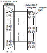
XW2Z-[][][]B, XW2Z-[][][][]BF-L
Connectors: One 40-pin Connector Made by Fujitsu Component, Ltd. to One 40-pin MIL Connector
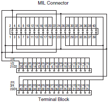
Wiring Diagram
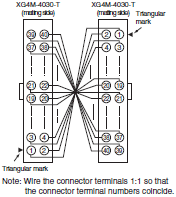
XW2Z-[][][]K, XW2Z-[][][][]FF-L
Connectors: One 40-pin Connector to One 40-pin MIL Connector
Wiring Diagram
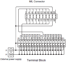
Push-in spring

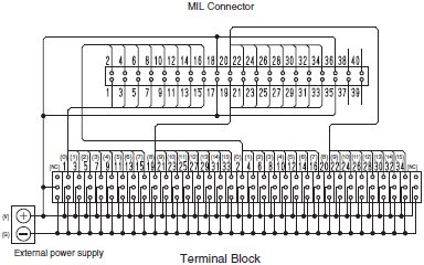
Wiring Diagram
XW2R-P16GD-C1-COM
XW2R-P16GD-C3-COM
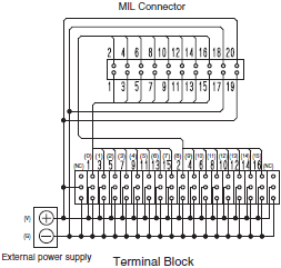
XW2R-P32GD-C1-COM
XW2R-P32GD-C2-COM
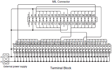
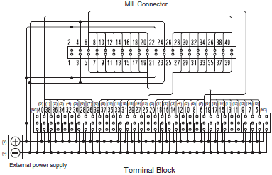
XW2R-P32GD-C3-COM

XW2R-P32GD-C4-COM
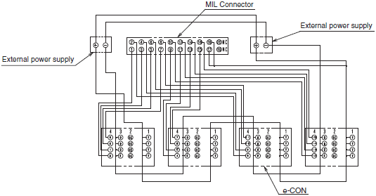
e-CON Type
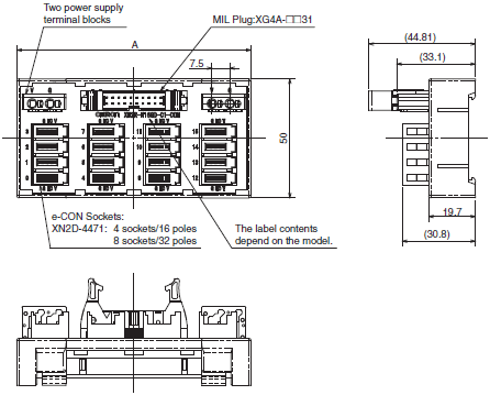
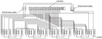
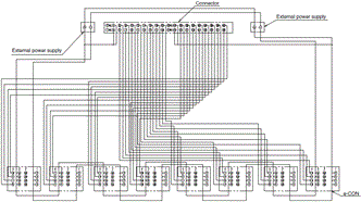
Wiring Diagram
XW2R-N16GD-C1-COM
XW2R-N32GD-C1-COM
XW2R-N32GD-C2-COM
without power supply terminals
Phillips screw
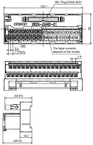
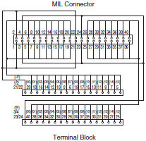
Wiring Diagram
XW2R-J34GD-C1
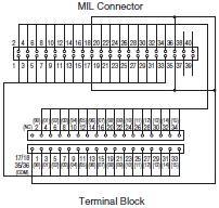
XW2R-J34GD-C2
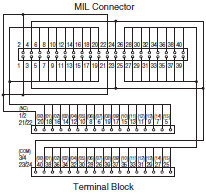
XW2R-J34GD-C3
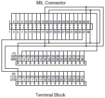
XW2R-J34GD-C4
Slotted screw (rise up)
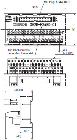
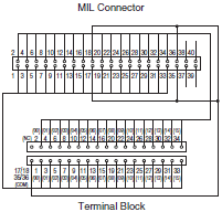
Wiring Diagram
XW2R-E34GD-C1
XW2R-E34GD-C2
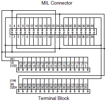
XW2R-E34GD-C3

XW2R-E34GD-C4
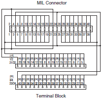
Push-in spring
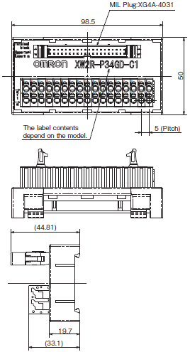
Wiring Diagram
XW2R-P34GD-C1
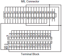
XW2R-P34GD-C2
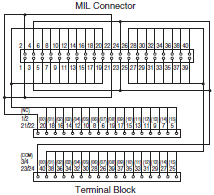
XW2R-P34GD-C3
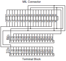
XW2R-P34GD-C4
Models for Connection to Mitsubishi PLCs
with power supply terminals
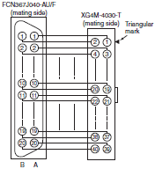
XW2Z-[][][]B, XW2Z-[][][][]BF-L
Connectors: One 40-pin Connector Made by Fujitsu Component, Ltd. to One 40-pin MIL Connector
Wiring Diagram
XW2Z-[][][]AA
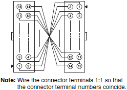
One 14-pin MIL Connector to One 14-pin MIL Connector
Wiring Diagram
XW2R-G32GD-M1-COM
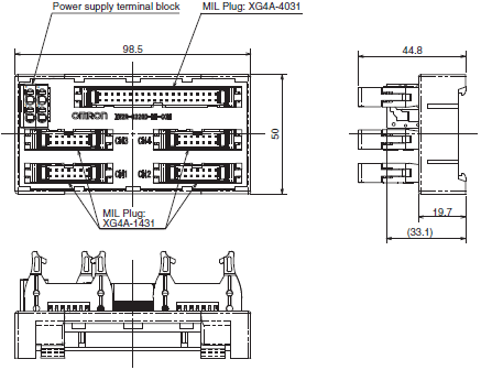
Wiring Diagram
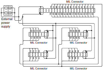
XW2R-N08GD-COM
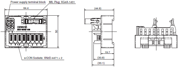
The e-CON address assignments are for combining the XW2R-G32GD-M1-COM with four XW2R-N08GD-COM.
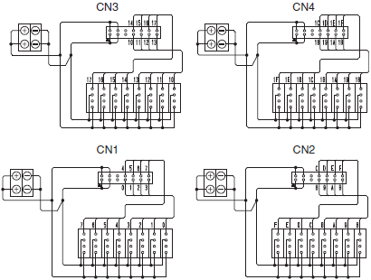
Wiring Diagram

Push-in spring
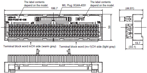
Wiring Diagram
XW2R-P32GD-M1-COM
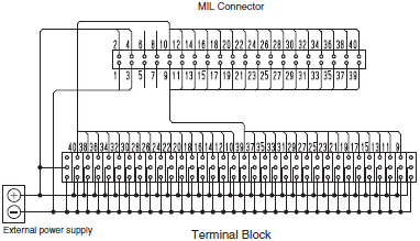
XW2R-P32GD-M2-COM
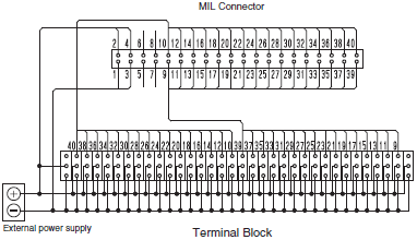
without power supply terminals
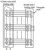
XW2Z-[][][]B, XW2Z-[][][][]BF-L
Connectors: One 40-pin Connector Made by Fujitsu Component, Ltd. to One 40-pin MIL Connector
Wiring Diagram
Phillips screw

Wiring Diagram
XW2R-J34GD-M1
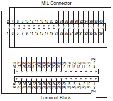
XW2R-J34GD-M2
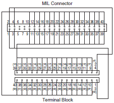
Slotted screw (rise up)
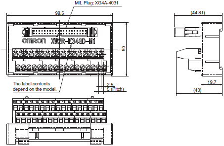
Wiring Diagram
XW2R-E34GD-M1
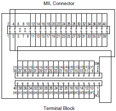
XW2R-E34GD-M2
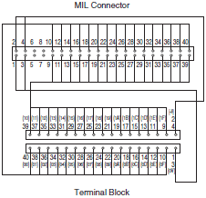
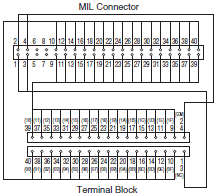
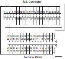
Push-in spring
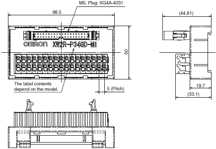
Wiring Diagram
XW2R-P34GD-M1
XW2R-P34GD-M2
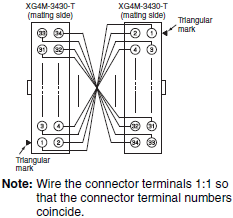
Models for Keyence PLCs
with power supply terminals
XW2Z-[][][]EE, XW2Z-[][][]EE-L
Connectors: One 34-pin MIL Connector to One 34-pin MIL Connector
Wiring Diagram
Push-in spring
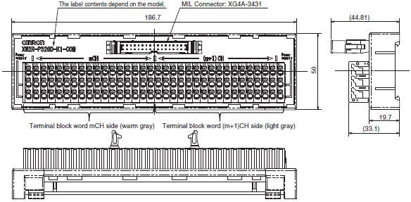
Wiring Diagram
XW2R-P32GD-K1-COM
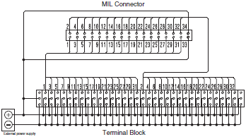
without power supply terminals
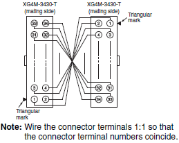
XW2Z-[][][]EE, XW2Z-[][][][]EE-L
Connectors: One 34-pin MIL Connector to One 34-pin MIL Connector
Wiring Diagram
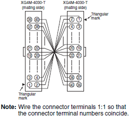
XW2Z-[][][]K, XW2Z-[][][][]FF-L
Connectors: One 40-pin MIL Connector to One 40-pin MIL Connector
Wiring Diagram
Phillips screw

Wiring Diagram
XW2R-J34GD-K1
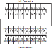
XW2R-J40GD-K2
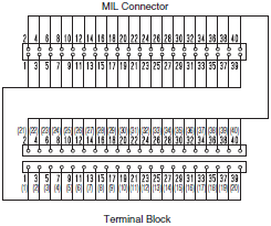
Push-in spring
Wiring Diagram
XW2R-P34GD-K1
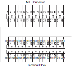
XW2R-P40GD-K2
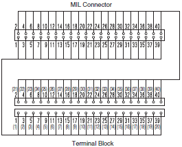
last update: January 07, 2015
OMRON XW2R (PLCs) lineup
XW2R (PLCs) Connector-Terminal Block Conversion Units for PLCs/Lineuplast update: April 2, 2018
Models for Connection to OMRON PLCs
with power supply terminals
Model List

Models for OMRON PLCs
Models with 16 Poles
| I/O | I/O Points | I/O Unit Model | Models that connect to PLCs | Connecting cables * |
|---|---|---|---|---|
| Input | 32 | CJ1W-ID231 | XW2R-P16GD-C1-COM: 2 pcs XW2R-N16GD-C1-COM: 2 pcs | XW2Z-[][][]D: 1 Cable |
| CS1W-ID231 | ||||
| 64 | CJ1W-ID261 | XW2R-P16GD-C1-COM: 4 pcs XW2R-N16GD-C1-COM: 4 pcs | XW2Z-[][][]D: 2 Cables | |
| CS1W-ID261 | ||||
| I/O | 16 | NX-MD6121-6 (inputs) | XW2R-P16GD-C1-COM: 1 pcs XW2R-N16GD-C1-COM: 1 pcs | XW2Z-[][][]A: 1 Cable |
| CJ1W-MD231 (inputs) | XW2R-P16GD-C1-COM: 1 pcs XW2R-N16GD-C1-COM: 1 pcs | XW2Z-[][][]A: 1 Cable | ||
| 32 | CJ1W-MD261 (inputs) | XW2R-P16GD-C1-COM: 2 pcs XW2R-N16GD-C1-COM: 2 pcs | XW2Z-[][][]D: 1 Cable | |
| CS1W-MD261 (inputs) | ||||
| CS1W-MD262 (inputs) | ||||
| CS1W-MD561 (inputs) | ||||
| Input | 32 | CJ1W-ID232 | XW2R-P16GD-C1-COM: 2 pcs XW2R-N16GD-C1-COM: 2 pcs | XW2Z-[][][]N: 1 Cable |
| CJ1W-ID233 | ||||
| I/O | CJ1W-MD263 (inputs) | |||
| CJ1W-MD563 (inputs) | ||||
| Input | 64 | CJ1W-ID262 | XW2R-P16GD-C1-COM: 4 pcs XW2R-N16GD-C1-COM: 4 pcs | XW2Z-[][][]N: 2 Cables |
| Output | 16 | NX-OD5121-5 | XW2R-P16GD-C3-COM: 1 pcs | XW2Z-[][][]X: 1 Cable |
| NX-OD5256-5 | ||||
| 32 | CJ1W-OD231 | XW2R-P16GD-C3-COM: 2 pcs | XW2Z-[][][]L: 1 Cable | |
| CS1W-OD231 | ||||
| CS1W-OD232 | ||||
| CJ1W-OD232 | XW2R-P16GD-C3-COM: 2 pcs | XW2Z-[][][]N: 1 Cables | ||
| CJ1W-OD233 | ||||
| CJ1W-OD234 | ||||
| 64 | CJ1W-OD261 | XW2R-P16GD-C3-COM: 4 pcs | XW2Z-[][][]L: 2 Cables | |
| CS1W-OD261 | ||||
| CJ1W-OD262 | XW2R-P16GD-C3-COM: 4 pcs | XW2Z-[][][]N: 2 Cables | ||
| CJ1W-OD263 | ||||
| I/O | 16 | NX-MD6121-6 (outputs) | XW2R-P16GD-C3-COM: 1 pcs | XW2Z-[][][]A: 1 Cable |
| CJ1W-MD231 (outputs) | XW2R-P16GD-C3-COM: 1 pcs | XW2Z-[][][]A: 1 Cable | ||
| 32 | CJ1W-MD261 (outputs) | XW2R-P16GD-C3-COM: 2 pcs | XW2Z-[][][]L: 1 Cable | |
| CS1W-MD261 (outputs) | ||||
| CS1W-MD262 (outputs) | ||||
| CS1W-MD561 (outputs) |
* [][][] is replaced by the cable length. Refer to "PLC Connecting Cables".
Note: Connection is not possible to all OMRON PLC Units.
This Connector-Terminal Block Conversion Unit is for NPN. For PNP, reverse the polarity of the external power
supply and I/O on the Connector-Terminal Block Conversion Unit.
Models with 32 Poles
| I/O | I/O Points | I/O Unit Model | Models that connect to PLCs | Connecting cables * |
|---|---|---|---|---|
| Input | 32 | NX-ID6142-5 | XW2R-P32GD-C2-COM: 1 pcs XW2R-N32GD-C2-COM: 1 pcs | XW2Z-[][][]K: 1 Cable, or XW2Z-[][][][]FF-L: 1 Cable |
| NX-ID6142-6 | XW2R-P32GD-C1-COM: 1 pcs XW2R-N32GD-C1-COM: 1 pcs | XW2Z-[][][]B: 1 Cable, or XW2Z-[][][][]BF-L: 1 Cable | ||
| CJ1W-ID231 | XW2R-P32GD-C1-COM: 1 pcs XW2R-N32GD-C1-COM: 1 pcs | XW2Z-[][][]B: 1 Cable, or XW2Z-[][][][]BF-L: 1 Cable | ||
| CS1W-ID231 | ||||
| 64 | CJ1W-ID261 | XW2R-P32GD-C1-COM: 2 pcs XW2R-N32GD-C1-COM: 2 pcs | XW2Z-[][][]B: 2 Cables, or XW2Z-[][][][]BF-L: 2 Cables | |
| CS1W-ID261 | ||||
| I/O | 32 | CJ1W-MD261 (inputs) | XW2R-P32GD-C1-COM: 1 pcs XW2R-N32GD-C1-COM: 1 pcs | XW2Z-[][][]B: 1 Cable, or XW2Z-[][][][]BF-L: 1 Cable |
| CS1W-MD261 (inputs) | ||||
| CS1W-MD262 (inputs) | ||||
| CS1W-MD561 (inputs) | ||||
| Input | 32 | CJ1W-ID232 | XW2R-P32GD-C2-COM: 1 pcs XW2R-N32GD-C2-COM: 1 pcs | XW2Z-[][][]K: 1 Cable, or XW2Z-[][][][]FF-L: 1 Cable |
| CJ1W-ID233 | ||||
| 64 | CJ1W-ID262 | XW2R-P32GD-C2-COM: 2 pcs XW2R-N32GD-C2-COM: 2 pcs | XW2Z-[][][]K: 2 Cables, or XW2Z-[][][][]FF-L: 2 Cables | |
| I/O | 32 | CJ1W-MD263 (inputs) | XW2R-P32GD-C2-COM: 1 pcs XW2R-N32GD-C2-COM: 1 pcs | XW2Z-[][][]K: 1 Cable, or XW2Z-[][][][]FF-L: 1 Cable |
| CJ1W-MD563 (inputs) | ||||
| Output | 32 | NX-OD6121-5 | XW2R-P32GD-C4-COM: 1 pcs | XW2Z-[][][]K: 1 Cable, or XW2Z-[][][][]FF-L: 1 Cable |
| NX-OD6256-5 | ||||
| NX-OD6121-6 | XW2R-P32GD-C3-COM: 1 pcs | XW2Z-[][][]B: 1 Cable, or XW2Z-[][][][]BF-L: 1 Cable | ||
| CJ1W-OD231 | XW2R-P32GD-C3-COM: 1 pcs | XW2Z-[][][]B: 1 Cable, or XW2Z-[][][][]BF-L: 1 Cable | ||
| CS1W-OD231 | ||||
| CS1W-OD232 | ||||
| 64 | CJ1W-OD261 | XW2R-P32GD-C3-COM: 2 pcs | XW2Z-[][][]B: 2 Cables, or XW2Z-[][][][]BF-L: 2 Cables | |
| CS1W-OD261 | ||||
| CS1W-OD262 | ||||
| I/O | 32 | CJ1W-MD261 (outputs) | XW2R-P32GD-C3-COM: 1 pcs | XW2Z-[][][]B: 1 Cable, or XW2Z-[][][][]BF-L: 1 Cable |
| CS1W-MD261 (outputs) | ||||
| CS1W-MD262 (outputs) | ||||
| CS1W-MD561 (outputs) | ||||
| Output | 32 | CJ1W-OD232 | XW2R-P32GD-C4-COM: 1 pcs | XW2Z-[][][]K: 1 Cable, or XW2Z-[][][][]FF-L: 1 Cable |
| CJ1W-OD233 | ||||
| CJ1W-OD234 | ||||
| 64 | CJ1W-OD262 | XW2R-P32GD-C4-COM: 2 pcs | XW2Z-[][][]K: 2 Cables, or XW2Z-[][][][]FF-L: 2 Cables | |
| CJ1W-OD263 | ||||
| I/O | 32 | CJ1W-MD263 (outputs) | XW2R-P32GD-C4-COM: 1 pcs | XW2Z-[][][]K: 1 Cable, or XW2Z-[][][][]FF-L: 1 Cable |
| CJ1W-MD563 (outputs) |
* [][][][] is replaced by the cable length. Refer to "PLC Connecting Cables".
Note: Connection is not possible to all OMRON PLC Units.
This Connector-Terminal Block Conversion Unit is for NPN. For PNP, reverse the polarity of the external power
supply and I/O on the Connector-Terminal Block Conversion Unit.
PLC Connecting Cables
XW2Z-[][][]B, XW2Z-[][][][]BF-L
Connectors: One 40-pin Connector Made by Fujitsu Component, Ltd. to One 40-pin MIL Connector
| Appearance | Cable length L (m) | With shield | Without shield |
|---|---|---|---|
| Model | Model | ||
 | 0.5 | XW2Z-050B | XW2Z-0050BF-L |
| 1 | XW2Z-100B | XW2Z-0100BF-L | |
| 1.5 | XW2Z-150B | XW2Z-0150BF-L | |
| 2 | XW2Z-200B | XW2Z-0200BF-L | |
| 3 | XW2Z-300B | XW2Z-0300BF-L | |
| 5 | XW2Z-500B | XW2Z-0500BF-L | |
| 7 | XW2Z-700B | XW2Z-0700BF-L | |
| 10 | XW2Z-010B | XW2Z-1000BF-L | |
| 15 | XW2Z-15MB | --- | |
| 20 | XW2Z-20MB | --- |
Cable length L (m)

XW2Z-[][][]K, XW2Z-[][][][]FF-L
Connectors: One 40-pin Connector to One 40-pin MIL Connector
| Appearance | Cable length L (m) | With shield | Without shield |
|---|---|---|---|
| Model | Model | ||
 | 0.25 | XW2Z-C25K | --- |
| 0.5 | XW2Z-C50K | XW2Z-0050FF-L | |
| 1 | XW2Z-100K | XW2Z-0100FF-L | |
| 1.5 | XW2Z-150K | XW2Z-0150FF-L | |
| 2 | XW2Z-200K | XW2Z-0200FF-L | |
| 3 | XW2Z-300K | XW2Z-0300FF-L | |
| 5 | XW2Z-500K | XW2Z-0500FF-L | |
| 7 | --- | XW2Z-0700FF-L | |
| 10 | XW2Z-010K | XW2Z-1000FF-L |
Cable length L (m)

Push-in spring
| Appearance ∗1 | I/O Points | Input/Output | Model ∗2 |
|---|---|---|---|
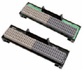 | 16 | Input | XW2R-P16GD-C1-COM |
| Output | XW2R-P16GD-C3-COM | ||
| 32 | Input | XW2R-P32GD-C1-COM | |
| XW2R-P32GD-C2-COM | |||
| Output | XW2R-P32GD-C3-COM | ||
| XW2R-P32GD-C4-COM |
*1 Input models (XW2R-P[][]GD-C1/C2-COM) are black and output models (XW2R-P[][]GD-C3/C4-COM) are green.
*2 Only DIN Track mounting models are described here. Refer to the XW2R-series Connector-Terminal Block Conversion Units Catalog (Cat. No. G077) for information on screw mounting models.
e-CON Type
| Appearance | I/O Points | Input/Output | Model |
|---|---|---|---|
 | 16 | Input | XW2R-N16GD-C1-COM |
| 32 | XW2R-N32GD-C1-COM | ||
| XW2R-N32GD-C2-COM |
without power supply terminals
Model List

Models for OMRON PLCs
| I/O | I/O Points | I/O Unit Model | Models that connect to PLCs *1 | Connecting cables *2 |
|---|---|---|---|---|
| Input | 32 | NX-ID6142-6 | XW2R-[]34GD-C1: 1 pcs | XW2Z-[][][]B: 1 Cable, or XW2Z-[][][][]BF-L: 1 Cable |
| CJ1W-ID231 | XW2R-[]34GD-C1: 1 pcs | XW2Z-[][][]B: 1 Cable, or XW2Z-[][][][]BF-L: 1 Cable | ||
| CS1W-ID231 | ||||
| 64 | CJ1W-ID261 | XW2R-[]34GD-C1: 2 pcs | XW2Z-[][][]B: 2 Cables, or XW2Z-[][][][]BF-L: 2 Cables | |
| CS1W-ID261 | ||||
| I/O | 32 | CJ1W-MD261 (inputs) | XW2R-[]34GD-C1: 1 pcs | XW2Z-[][][]B: 1 Cable, or XW2Z-[][][][]BF-L: 1 Cable |
| CS1W-MD261 (inputs) | ||||
| CS1W-MD262 (inputs) | ||||
| CS1W-MD561 (inputs) | ||||
| Input | 32 | NX-ID6142-5 | XW2R-[]34GD-C2: 1 pcs | XW2Z-[][][]K: 1 Cable, or XW2Z-[][][][]FF-L: 1 Cable |
| CJ1W-ID232 | XW2R-[]34GD-C2: 1 pcs | XW2Z-[][][]K: 1 Cable, or XW2Z-[][][][]FF-L: 1 Cable | ||
| CJ1W-ID233 | ||||
| 64 | CJ1W-ID262 | XW2R-[]34GD-C2: 2 pcs | XW2Z-[][][]K: 2 Cables, or XW2Z-[][][][]FF-L: 2 Cables | |
| I/O | 32 | CJ1W-MD263 (inputs) | XW2R-[]34GD-C2: 1 pcs | XW2Z-[][][]K: 1 Cable, or XW2Z-[][][][]FF-L: 1 Cable |
| CJ1W-MD563 (inputs) | ||||
| Output | 32 | NX-OD6121-6 | XW2R-[]34GD-C3: 1 pcs | XW2Z-[][][]B: 1 Cable, or XW2Z-[][][][]BF-L: 1 Cable |
| CJ1W-OD231 | XW2R-[]34GD-C3: 1 pcs | XW2Z-[][][]B: 1 Cable, or XW2Z-[][][][]BF-L: 1 Cable | ||
| CS1W-OD231 | ||||
| CS1W-OD232 | ||||
| 64 | CJ1W-OD261 | XW2R-[]34GD-C3: 2 pcs | XW2Z-[][][]B: 2 Cables, or XW2Z-[][][][]BF-L: 2 Cables | |
| CS1W-OD261 | ||||
| CS1W-OD262 | ||||
| I/O | 32 | CJ1W-MD261 (outputs) | XW2R-[]34GD-C3: 1 pcs | XW2Z-[][][]B: 1 Cable, or XW2Z-[][][][]BF-L: 1 Cable |
| CS1W-MD261 (outputs) | ||||
| CS1W-MD262 (outputs) | ||||
| CS1W-MD561 (outputs) | ||||
| Output | 32 | NX-OD6121-5 | XW2R-[]34GD-C4: 1 pcs | XW2Z-[][][]K: 1 Cable, or XW2Z-[][][][]FF-L: 1 Cable |
| NX-OD6256-5 | ||||
| CJ1W-OD232 | XW2R-[]34GD-C4: 1 pcs | XW2Z-[][][]K: 1 Cable, or XW2Z-[][][][]FF-L: 1 Cable | ||
| CJ1W-OD233 | ||||
| CJ1W-OD234 | ||||
| 64 | CJ1W-OD262 | XW2R-[]34GD-C4: 2 pcs | XW2Z-[][][]K: 2 Cables, or XW2Z-[][][][]FF-L: 2 Cables | |
| CJ1W-OD263 | ||||
| I/O | 32 | CJ1W-MD263 (outputs) | XW2R-[]34GD-C4: 1 pcs | XW2Z-[][][]K: 1 Cable, or XW2Z-[][][][]FF-L: 1 Cable |
| CJ1W-MD563 (outputs) |
*1 Replace the box ([]) with the wiring method code (J, E, or P).
*2 [][][][] is replaced by the cable length. For details, refer to Data Sheet.
Note: 1. Connection is not possible to all OMRON PLC Units.
2. There is one common for each 32 points.
Phillips screw
| Appearance | I/O Points (Number of poles) | Model ∗ |
|---|---|---|
 | 32 (34) | XW2R-J34GD-C1 |
| XW2R-J34GD-C2 | ||
| XW2R-J34GD-C3 | ||
| XW2R-J34GD-C4 |
* Only DIN Track mounting models are described here. Refer to the XW2R-series Connector-Terminal Block Conversion Units Catalog (Cat. No. G077) for information on screw mounting models.
Slotted screw (rise up)
| Appearance | I/O Points (Number of poles) | Model ∗ |
|---|---|---|
 | 32 (34) | XW2R-E34GD-C1 |
| XW2R-E34GD-C2 | ||
| XW2R-E34GD-C3 | ||
| XW2R-E34GD-C4 |
* Only DIN Track mounting models are described here. Refer to the XW2R-series Connector-Terminal Block Conversion Units Catalog (Cat. No. G077) for information on screw mounting models.
Push-in spring
| Appearance | I/O Points (Number of poles) | Model ∗ |
|---|---|---|
 | 32 (34) | XW2R-P34GD-C1 |
| XW2R-P34GD-C2 | ||
| XW2R-P34GD-C3 | ||
| XW2R-P34GD-C4 |
* Only DIN Track mounting models are described here. Refer to the XW2R-series Connector-Terminal Block Conversion Units Catalog (Cat. No. G077) for information on screw mounting models.
Models for Connection to Mitsubishi PLCs
with power supply terminals
Model List

Models for Connection to Mitsubishi PLCs
| PLC Type | I/O Points | Mitsubishi PLC Module model | Models that connect to PLCs | Connecting cables * |
|---|---|---|---|---|
| M1 | 32 | LX41C4 | XW2R-P32GD-M1-COM: 1 pcs | XW2Z-[][][]B: 1 Cable, or XW2Z-[][][][]BF-L: 1 Cable |
| QX41/QX41-S1/QX41-S2 | ||||
| QX71 | ||||
| RX41C4 | ||||
| QH42P (Input) | ||||
| QX41Y41P (Input) | ||||
| RH42C4NT2P (Input) | ||||
| 64 | LX42C4 | XW2R-P32GD-M1-COM: 2 pcs | XW2Z-[][][]B: 2 Cables, or XW2Z-[][][][]BF-L: 2 Cables | |
| QX42/QX42-S1 | ||||
| QX82/QX82-S1 | ||||
| RX42C4 | ||||
| M2 | 32 | LY41NT1P | XW2R-P32GD-M2-COM: 1 pcs | XW2Z-[][][]B: 1 Cable, or XW2Z-[][][][]BF-L: 1 Cable |
| QY41P | ||||
| QY71 | ||||
| RY41NT2P | ||||
| RY41PT1P | ||||
| QH42P (Output) | ||||
| QX41Y41P (Output) | ||||
| RH42C4NT2P (Output) | ||||
| 64 | LY42NT1P | XW2R-P32GD-M2-COM: 2 pcs | XW2Z-[][][]B: 2 Cables, or XW2Z-[][][][]BF-L: 2 Cables | |
| QY42P | ||||
| QY82P | ||||
| RY42NT2P | ||||
| RY42PT1P |
* [][][][] is replaced by the cable length.
Note: This Connector-Terminal Block Conversion Unit is for NPN. For PNP, reverse the polarity of the external power
supply and I/O on the Connector-Terminal Block Conversion Unit.
XW2Z-[][][]B, XW2Z-[][][][]BF-L
Connectors: One 40-pin Connector Made by Fujitsu Component, Ltd. to One 40-pin MIL Connector
| Appearance | Cable length L (m) | With shield | Without shield |
|---|---|---|---|
| Model | Model | ||
 | 0.5 | XW2Z-050B | XW2Z-0050BF-L |
| 1 | XW2Z-100B | XW2Z-0100BF-L | |
| 1.5 | XW2Z-150B | XW2Z-0150BF-L | |
| 2 | XW2Z-200B | XW2Z-0200BF-L | |
| 3 | XW2Z-300B | XW2Z-0300BF-L | |
| 5 | XW2Z-500B | XW2Z-0500BF-L | |
| 7 | XW2Z-700B | XW2Z-0700BF-L | |
| 10 | XW2Z-010B | XW2Z-1000BF-L | |
| 15 | XW2Z-15MB | --- | |
| 20 | XW2Z-20MB | --- |
Cable length L (m)

MIL Connector
Models for Connection to Mitsubishi PLCs
| I/O Points | Model | Models that connect to PLCs | Connecting cables * |
|---|---|---|---|
| 32 | QX41, QX41-S1, QX41-S2, QX71 | XW2R-G32GD-M1-COM: 1 pcs | Connection A XW2Z-[][][]B: 1 Cable, or XW2Z-[][][][]BF-L: 1 Cable Connection B XW2Z-[][][]AA: 4 Cables |
| QH42P (Input) , QX41Y41P (Input) | |||
| LX41C4 | |||
| 64 | QX42, QX42-S1, QX82, QX82-S1 | XW2R-G32GD-M1-COM: 2 pcs | Connection A XW2Z-[][][]B: 2 Cables, or XW2Z-[][][][]BF-L: 2 Cables Connection B XW2Z-[][][]AA: 8 Cables |
| LX42C4 |
* [][][][] is replaced by the cable length.
Note: Refer to Data Sheet for information on the XW2Z-[][][]B and XW2Z-[][][][]BF-L.
This Connector-Terminal Block Conversion Unit is for NPN. For PNP,reverse the polarity of the external power
supply and I/O on the Connector-Terminal Block Conversion Unit.
XW2Z-[][][]AA
One 14-pin MIL Connector to One 14-pin MIL Connector
| Appearance | Cable length L (m) | With shield |
|---|---|---|
| Model | ||
 | 0.5 | XW2Z-050AA |
| 1 | XW2Z-100AA | |
| 2 | XW2Z-200AA | |
| 5 | XW2Z-500AA | |
| 10 | XW2Z-010AA |
Cable length L (m)

| Appearance | Model | Number of poles |
|---|---|---|
 | XW2R-G32GD-M1-COM | 40 poles x 1 point 14 poles x 4 points |
| Appearance | I/O Points | Number of poles (PLC end) | I/O | Model | Mounted Connector model | Cable Connector model |
|---|---|---|---|---|---|---|
 | 8 points | 14 poles | Input | XW2R-N08GD-COM | XG4A-1431 (PLC end) XN2D-4471 (for input) | XG4M-1430-T (PLC end) XN2A-1470 (for input) |
Push-in spring
| Appearance | I/O Points | Input/Output | Model |
|---|---|---|---|
 | 32 points | Input | XW2R-P32GD-M1-COM |
| Output | XW2R-P32GD-M2-COM |
without power supply terminals
Model List

Models for Connection to Mitsubishi PLCs
| PLC Type | I/O Points | Mitsubishi PLC Module model | Models that connect to PLCs *1 | Connecting cables *2 |
|---|---|---|---|---|
| M1 | 32 | LX41C4 | XW2R-[]34GD-M1: 1 pcs | XW2Z-[][][]B: 1 Cable, or XW2Z-[][][]BF-L: 1 Cable |
| QX41/QX41-S1/QX41-S2 | ||||
| QX71 | ||||
| RX41C4 | ||||
| QH42P (Input) | ||||
| QX41Y41P (Input) | ||||
| RH42C4NT2P (Input) | ||||
| 64 | LX42C4 | XW2R-[]34GD-M1: 2 pcs | XW2Z-[][][]B: 2 Cables, or XW2Z-[][][][]BF-L: 2 Cables | |
| QX42/QX42-S1 | ||||
| QX82/QX82-S1 | ||||
| RX42C4 | ||||
| M2 | 32 | LY41NT1P | XW2R-[]34GD-M2: 1 pcs | XW2Z-[][][]B: 1 Cable, or XW2Z-[][][][]BF-L: 1 Cable |
| QY41P | ||||
| QY71 | ||||
| RY41NT2P | ||||
| RY41PT1P | ||||
| QH42P (Output) | ||||
| QX41Y41P (Output) | ||||
| RH42C4NT2P (Output) | ||||
| 64 | LY42NT1P | XW2R-[]34GD-M2: 2 pcs | XW2Z-[][][]B: 2 Cables, or XW2Z-[][][][]BF-L: 1 Cable | |
| QY42P | ||||
| QY82P | ||||
| RY42NT2P | ||||
| RY42PT1P |
*1 Replace the box ([]) with the wiring method code (J, E, or P).
*2 [][][][] is replaced by the cable length.
XW2Z-[][][]B, XW2Z-[][][][]BF-L
Connectors: One 40-pin Connector Made by Fujitsu Component, Ltd. to One 40-pin MIL Connector
| Appearance | Cable length L (m) | With shield | Without shield |
|---|---|---|---|
| Model | Model | ||
 | 0.5 | XW2Z-050B | XW2Z-0050BF-L |
| 1 | XW2Z-100B | XW2Z-0100BF-L | |
| 1.5 | XW2Z-150B | XW2Z-0150BF-L | |
| 2 | XW2Z-200B | XW2Z-0200BF-L | |
| 3 | XW2Z-300B | XW2Z-0300BF-L | |
| 5 | XW2Z-500B | XW2Z-0500BF-L | |
| 7 | XW2Z-700B | XW2Z-0700BF-L | |
| 10 | XW2Z-010B | XW2Z-1000BF-L | |
| 15 | XW2Z-15MB | --- | |
| 20 | XW2Z-20MB | --- |
Cable length L (m)

Phillips screw
| Appearance | I/O Points (Number of poles) | Model ∗ |
|---|---|---|
 | 32 (34) | XW2R-J34GD-M1 |
| XW2R-J34GD-M2 |
* Only DIN Track mounting models are described here. Refer to the XW2R-series Connector-Terminal Block Conversion Units Catalog (Cat. No. G077) for information on screw mounting models.
Slotted screw (rise up)
| Appearance | I/O Points (Number of poles) | Model ∗ |
|---|---|---|
 | 32 (34) | XW2R-E34GD-M1 |
| XW2R-E34GD-M2 |
* Only DIN Track mounting models are described here. Refer to the XW2R-series Connector-Terminal Block Conversion Units Catalog (Cat. No. G077) for information on screw mounting models.
Push-in spring
| Appearance | I/O Points (Number of poles) | Model ∗ |
|---|---|---|
 | 32 (34) | XW2R-P34GD-M1 |
| XW2R-P34GD-M2 |
* Only DIN Track mounting models are described here. Refer to the XW2R-series Connector-Terminal Block Conversion Units Catalog (Cat. No. G077) for information on screw mounting models.
Models for Keyence PLCs
with power supply terminals
Model List

Models for Keyence PLCs
| I/O | I/O Points | Unit | Models for Keyence PLCs | Models that connect to PLCs | Connecting cables * |
|---|---|---|---|---|---|
| Input | 32 | Input Unit Model | KV-C32XA, KV-C32XC | XW2R-P32GD-K1-COM: 1 pcs | XW2Z-[][][]EE: 1 Cable, or XW2Z-[][][][]EE-L: 1 Cable |
| 64 | KV-C64XA, KV-C64XB, KV-C64XC | XW2R-P32GD-K1-COM: 2 pcs | XW2Z-[][][]EE: 2 Cables, or XW2Z-[][][][]EE-L: 2 Cables |
* [][][][] is replaced by the cable length.
Note: This Connector-Terminal Block Conversion Unit is for NPN. For PNP,reverse the polarity of the external power
supply and I/O on the Connector-Terminal Block Conversion Unit.
XW2Z-[][][]EE, XW2Z-[][][]EE-L
Connectors: One 34-pin MIL Connector to One 34-pin MIL Connector
| Appearance | Cable length L (m) | With shield | Without shield |
|---|---|---|---|
| Model | Model | ||
 | 0.5 | XW2Z-050EE | XW2Z-0050EE-L |
| 1 | XW2Z-100EE | XW2Z-0100EE-L | |
| 1.5 | XW2Z-150EE | XW2Z-0150EE-L | |
| 2 | XW2Z-200EE | XW2Z-0200EE-L | |
| 3 | XW2Z-300EE | XW2Z-0300EE-L | |
| 5 | XW2Z-500EE | XW2Z-0500EE-L | |
| 7 | --- | XW2Z-0700EE-L | |
| 10 | --- | XW2Z-1000EE-L |
Cable length L (m)

Push-in spring
| Appearance | I/O Points | Model |
|---|---|---|
 | 32 | XW2R-P32GD-K1-COM |
without power supply terminals
Model List

Models for Keyence PLCs
| I/O | I/O Points | Unit | Models for Keyence PLCs | Models that connect to PLCs *1 | Connecting cables *2 |
|---|---|---|---|---|---|
| Input | 32 | I/O Unit Model | KV-C32XA, KV-C32XC | XW2R-[]34GD-K1: 1 pcs | XW2Z-[][][]EE: 1 Cable, or XW2Z-[][][][]EE-L: 1 Cable |
| Output | KV-C32TA, KV-C32TC, KV-C32TCP | ||||
| KV-C32TD | |||||
| I/O | KV-C32XTD | ||||
| Input | 64 | KV-C64XA, KV-C64XB, KV-C64XC | XW2R-[]34GD-K1: 2 pcs | XW2Z-[][][]EE: 2 Cables, or XW2Z-[][][][]EE-L: 2 Cables | |
| Output | KV-C64TA, KV-C64TC, KV-C64TD, KV-C64TCP | ||||
| --- | --- | CPU Unit Model | KV-1000, KV-3000, KV-5000, KV-5500 | XW2R-[]40GD-K2: 1 pcs | XW2Z-[][][]K: 1 Cable, or XW2Z-[][][][]FF-L: 1 Cable |
*1 Replace the box ([]) with the wiring method code (J or P).
*2 [][][][] is replaced by the cable length.
XW2Z-[][][]EE, XW2Z-[][][][]EE-L
Connectors: One 34-pin MIL Connector to One 34-pin MIL Connector
| Appearance | Cable length L (m) | With shield | Without shield |
|---|---|---|---|
| Model | Model | ||
 | 0.5 | XW2Z-050EE | XW2Z-0050EE-L |
| 1 | XW2Z-100EE | XW2Z-0100EE-L | |
| 1.5 | XW2Z-150EE | XW2Z-0150EE-L | |
| 2 | XW2Z-200EE | XW2Z-0200EE-L | |
| 3 | XW2Z-300EE | XW2Z-0300EE-L | |
| 5 | XW2Z-500EE | XW2Z-0500EE-L | |
| 7 | --- | XW2Z-0700EE-L | |
| 10 | --- | XW2Z-1000EE-L |
Cable length L (m)

XW2Z-[][][]K, XW2Z-[][][][]FF-L
Connectors: One 40-pin MIL Connector to One 40-pin MIL Connector
| Appearance | Cable length L (m) | With shield | Without shield |
|---|---|---|---|
| Model | Model | ||
 | 0.25 | XW2Z-C25K | --- |
| 0.5 | XW2Z-C50K | XW2Z-0050FF-L | |
| 1 | XW2Z-100K | XW2Z-0100FF-L | |
| 1.5 | XW2Z-150K | XW2Z-0150FF-L | |
| 2 | XW2Z-200K | XW2Z-0200FF-L | |
| 3 | XW2Z-300K | XW2Z-0300FF-L | |
| 5 | XW2Z-500K | XW2Z-0500FF-L | |
| 7 | --- | XW2Z-0700FF-L | |
| 10 | XW2Z-010K | XW2Z-1000FF-L |
Cable length L (m)

Phillips screw
| Appearance | I/O Points (Number of poles) | Model ∗ |
|---|---|---|
 | 32 (34) | XW2R-J34GD-K1 |
| 36 (40) | XW2R-J40GD-K2 |
* Only DIN Track mounting models are described here. Refer to the XW2R-series Connector-Terminal Block Conversion Units Catalog (Cat. No. G077) for information on screw mounting models.
Push-in spring
| Appearance | I/O Points (Number of poles) | Model ∗ |
|---|---|---|
 | 32 (34) | XW2R-P34GD-K1 |
| 36 (40) | XW2R-P40GD-K2 |
* Only DIN Track mounting models are described here. Refer to the XW2R-series Connector-Terminal Block Conversion Units Catalog (Cat. No. G077) for information on screw mounting models.
Input Device Connectors: XN2 e-CON Connectors
For Sensor
| Appearance | Number of poles | Model |
|---|---|---|
 | 4 | XN2A-1470 |
Relay Connector
| Appearance | Number of poles | Model |
|---|---|---|
 | 4 | XN2B-1470 |
last update: April 2, 2018
- NO. XW2R (PLCs)
- TYPE:Wiring Systems Connector-Terminal Block Conversion Units
 Copyright Statement
 - DATE:2021-06-08
- Associated products:
M7E (80 / 120 / 200 mm) Digital Display (80/120/200 mm)/Features XW2R (General-purpose devices) Connector-Terminal Block Conversion Units for General-purpose Devices/Features