
OMRON XW5T-PPower Supplies / In Addition/ Wiring Systems/DIN Track Terminal Blocks
OMRON XW5T-P Power Supplies / In Addition
OMRON XW5T-P Dimensions
/Images/l_3480-25-257945-198x198.jpglast update: April 3, 2017
New Value For Control Panels
Control Panels: The Heart of Manufacturing Sites.
Evolution in control panels results in large evolution in production facilities.
And if control panel design, control panel manufacturing processes, and human interaction with them are innovated, control panel manufacturing becomes simpler and takes a leap forward.
OMRON will continue to achieve a control panel evolution and process innovation through many undertakings starting with the shared Value Design for Panel *1 concept for the specifications of products used in control panels.

*1 Value Design for Panel
Our shared Value Design for Panel (herein after referred to as "Value Design") concept for the specifications of products used in control panels will create new value to our customer’s control panels.
Combining multiple products that share the Value Design concept will further increase the value provided to control panels.
OMRON Products from Terminal Blocks to Controllers Let You Efficiently Build Control Panels
Control panels can be downsized by using the many OMRON Controllers,
Power Supply, Relays, and other products that connect to the Terminal Blocks.
We will help you downsize control panels with OMRON control panel components that connect to terminal blocks.
We can also help you reduce terminal preparation and wiring work and reduce stock management work by maximizing the use of the components to unify tools and wires.
Everything from DIN Track Terminal Blocks to Controllers Available with Push-in Plus Terminal Blocks

Push-In Plus Terminal Blocks for Easy Wiring
Just Insert Wires: No Tools Required Now you can use Push-In Plus terminal blocks to reduce the time and work involved in wiring.
Greatly Reduce Wiring Work with Push-In Plus Terminal Blocks

Easy to Insert
OMRON’s Push-In Plus terminal blocks are as easy as inserting to an earphone jack. They help reduce the work load and improve wiring quality.
Held Firmly in Place
Even though less insertion force is required, the wires are held firmly in place. The advanced mechanism design technology and manufacturing technology produced a spring that ensures better workability and reliability.

No Retightening Required
The retightening that is required for screw terminal blocks is not required for Push-in Plus terminal blocks.
Your work load is reduced not only when wiring, but also for inspections, delivery (shipping), and maintenance.

Wiring Possible with Stranded Wires
You can insert wires with pin terminals or ferrules, or you can also insert solid wires or stranded wires.
When a stranded wire is used: 3 Steps.

Screwdriver Held in Place to Free Both Your Hands
Optimized shape to hold the screwdriver was created by the resin parts and the spring.
Work goes smoothly when connecting stranded wires directly to the terminal because it’s easier to aim at the desired terminal.

Safety
The structure provides finger protection so that your fingers never touch conductive parts.
Minimum Width of 3.5 mm to Help Downsize Control Panels
Terminal blocks are the most numerous, most space-eating components in control panels. OMRON has achieved the top class
*According to OMRON investigation in March 2017.

Web Service That Helps Reduce Work in Selecting Terminal Blocks and Designing
• If you use OMRON’s website, you can easily select the Terminal Blocks to connect to the control panel
components that you have selected.
• You can easily confirm the dimensions of the Terminal Blocks that you have selected.
• And you can easily create Terminal Block parts lists (BOMs) and marking formats.

Take a Look Now! (www.ia.omron.com/solution/panel/)
last update: April 3, 2017
Purchase the OMRON DIN Track Terminal Blocks Please fill in the following
If you have just landed here, this product OMRON XW5T-P Power Supplies / In Addition,Power Supplies / In Addition is offered online by Tianin FLD Technical Co.,Ltd. This is an online store providing Power Supplies / In Addition at wholesale prices for consumers. You can call us or send enquiry, we would give you the prices, packing,deliverty and more detailed information on the XW5T-P We cooperate with DHL,TNT,FEDEX,UPS,EMS,etc.They guarantee to meet your needs in terms of time and money,even if you need your OMRON XW5T-PPower Supplies / In Addition tomorrow morning (aka overnight or next day air) on your desk, 2, 3 days or more.Note to international customers, YES, we ship worldwide.
E8Y Differential Pressure Sensor/Features
CS1W-CIF31 USB-Serial Conversion Cable/Features
E2E-[]-IL[] IO-Link Proximity Sensor (Standard Models)/Features
CRT1-TS04T / TS04P Temperature Input Units/Features
XS2 Round Water-resistant Connectors (M12 Threads)/Features
OMRON XW5T-P lineup
XW5T-P DIN Track Push-in Terminal Blocks/Lineuplast update: April 3, 2017
Model Number Legend

Ordering Information
| Classification | Product Type | Nominal Cross Section (mm2) | Number of levels | Number of cramp position per level | Color | Weight (gram) | Model |
|---|---|---|---|---|---|---|---|
| Feed Through Terminal Blocks | Standard terminals | 1.0 | 1 | 2 | Dark gray | 3.3 | XW5T-P1.5-1.1-1 |
| 2.5 | 1 | 2 | 6.3 | XW5T-P2.5-1.1-1 | |||
| 4.0 | 1 | 2 | 8.4 | XW5T-P4.0-1.1-1 | |||
| 1.0 | 1 | 2 | Blue | 3.3 | XW5T-P1.5-1.1-1BL | ||
| 2.5 | 1 | 2 | 6.3 | XW5T-P2.5-1.1-1BL | |||
| 4.0 | 1 | 2 | 8.4 | XW5T-P4.0-1.1-1BL | |||
| Multi tiers terminal | 1.0 | 2 | 2 | Dark gray | 6.5 | XW5T-P1.5-1.1-2 | |
| 2.5 | 2 | 2 | 12.5 | XW5T-P2.5-1.1-2 | |||
| 4.0 | 2 | 2 | 16.5 | XW5T-P4.0-1.1-2 | |||
| 1.0 | 2 | 2 | Blue | 6.5 | XW5T-P1.5-1.1-2BL | ||
| 2.5 | 2 | 2 | 12.5 | XW5T-P2.5-1.1-2BL | |||
| 4.0 | 2 | 2 | 16.5 | XW5T-P4.0-1.1-2BL | |||
| Multi conductor terminals | 1.0 | 1 | 3 | Dark gray | 4.1 | XW5T-P1.5-1.2-1 | |
| 2.5 | 1 | 3 | 8.2 | XW5T-P2.5-1.2-1 | |||
| 4.0 | 1 | 3 | 10.8 | XW5T-P4.0-1.2-1 | |||
| 1.0 | 1 | 3 | Blue | 4.1 | XW5T-P1.5-1.2-1BL | ||
| 2.5 | 1 | 3 | 8.2 | XW5T-P2.5-1.2-1BL | |||
| 4.0 | 1 | 3 | 10.8 | XW5T-P4.0-1.2-1BL | |||
| 1.0 | 1 | 4 | Dark gray | 4.9 | XW5T-P1.5-2.2-1 | ||
| 2.5 | 1 | 4 | 10.4 | XW5T-P2.5-2.2-1 | |||
| 4.0 | 1 | 4 | 13.4 | XW5T-P4.0-2.2-1 | |||
| 1.0 | 1 | 4 | Blue | 4.9 | XW5T-P1.5-2.2-1BL | ||
| 2.5 | 1 | 4 | 10.4 | XW5T-P2.5-2.2-1BL | |||
| 4.0 | 1 | 4 | 13.4 | XW5T-P4.0-2.2-1BL | |||
| Grounding Terminal Blocks | Standard terminals | 1.0 | 1 | 2 | Green/ yellow | 4.7 | XW5G-P1.5-1.1-1 |
| 2.5 | 1 | 2 | 9.9 | XW5G-P2.5-1.1-1 | |||
| 4.0 | 1 | 2 | 11.8 | XW5G-P4.0-1.1-1 | |||
| Multi tiers terminal | 1.0 | 2 | 2 | 8.1 | XW5G-P1.5-1.1-2 | ||
| 2.5 | 2 | 2 | 16.6 | XW5G-P2.5-1.1-2 | |||
| 4.0 | 2 | 2 | 20.8 | XW5G-P4.0-1.1-2 | |||
| Multi conductor terminals | 1.0 | 1 | 3 | 5.5 | XW5G-P1.5-1.2-1 | ||
| 2.5 | 1 | 3 | 11.6 | XW5G-P2.5-1.2-1 | |||
| 4.0 | 1 | 3 | 14.1 | XW5G-P4.0-1.2-1 | |||
| 1.0 | 1 | 4 | 6.3 | XW5G-P1.5-2.2-1 | |||
| 2.5 | 1 | 4 | 13.8 | XW5G-P2.5-2.2-1 | |||
| 4.0 | 1 | 4 | 16.7 | XW5G-P4.0-2.2-1 |
Accessories
Short Bars
For XW5T-P1.5-[] or XW5G-P1.5-[]
| Appearance | No. of poles | Colors | Model* | Application |
|---|---|---|---|---|
 | 2 | Red (RD) Blue (BL) Yellow (YL) | XW5S-P1.5-2[] | Used for cross-over wiring between Terminal Blocks. |
| 3 | XW5S-P1.5-3[] | |||
| 4 | XW5S-P1.5-4[] | |||
| 5 | XW5S-P1.5-5[] | |||
| 10 | XW5S-P1.5-10[] |
* Replace the box ([]) in the model number with the code for the covering color. Specify the color: RD = red, BL = blue, YL = yellow
For XW5T-P2.5-[] or XW5G-P2.5-[]
| Appearance | No. of poles | Colors | Model* | Application |
|---|---|---|---|---|
 | 2 | Red (RD) Blue (BL) Yellow (YL) | XW5S-P2.5-2[] | Used for cross-over wiring between Terminal Blocks. |
| 3 | XW5S-P2.5-3[] | |||
| 4 | XW5S-P2.5-4[] | |||
| 5 | XW5S-P2.5-5[] | |||
| 10 | XW5S-P2.5-10[] |
* Replace the box ([]) in the model number with the code for the covering color. Specify the color: RD = red, BL = blue, YL = yellow
For XW5T-P4.0-[] or XW5G-P4.0-[]
| Appearance | No. of poles | Colors | Model* | Application |
|---|---|---|---|---|
 | 2 | Red (RD) Blue(BL) Yellow (YL) | XW5S-P4.0-2[] | Used for cross-over wiring between Terminal Blocks. |
| 3 | XW5S-P4.0-3[] | |||
| 4 | XW5S-P4.0-4[] | |||
| 5 | XW5S-P4.0-5[] | |||
| 10 | XW5S-P4.0-10[] |
* Replace the box ([]) in the model number with the code for the covering color. Specify the color: RD = red, BL = blue, YL = yellow
Labels
| Appearance | Applicable Terminal Blocks | Model | Minimum order in sheets (quantity per sheet) | Application |
|---|---|---|---|---|
 | XW5[]-P1.5-[] | XW5Z-P1.5LB1 | 5 sheets with 102 top labels per sheet | Used to identify wiring. (Material: PA resin, blank) |
| XW5Z-P1.5LB2 | 5 sheets with 108 side labels per sheet | |||
| XW5[]-P2.5-[] | XW5Z-P2.5LB1 | 5 sheets with 72 top labels per sheet | ||
| XW5Z-P2.5LB2 | 5 sheets with 72 side labels per sheet | |||
| XW5[]-P4.0-[] | XW5Z-P4.0LB1 | 5 sheets with 60 top labels per sheet | ||
| XW5Z-P4.0LB2 | 5 sheets with 60 side labels per sheet |
Note:
1. Different models are used for the top and side surfaces.
2. There is no place to mount the Top-surface Labels on Two-tier Terminal Blocks with a width of 3.5 mm, so they cannot be used.
3. If you use commercially available nameplates (9.5 mm width and 0.5 mm thickness), you can use a commercially available printer. Check with the manufacturer of the nameplates for information on applicable printers.
4. Refer to Data Sheet for details on printing labels.
End Cover
| Appearance | Applicable Terminal Blocks | Model | Application |
|---|---|---|---|
 | XW5[]-P1.5-1.1-1 | XW5E-P1.5-1.1-1 | This part is required to prevent electric shock. Always mount End Covers to the following locations when you use Terminal Blocks. (For details, refer to Data Sheet.) • Exposed metal surface of the last Terminal Block • Any Terminal Block that is next to a different shape of Terminal Block |
| XW5[]-P1.5-1.1-2 | XW5E-P1.5-1.1-2 | ||
| XW5[]-P1.5-1.2-1 | XW5E-P1.5-1.2-1 | ||
| XW5[]-P1.5-2.2-1 | XW5E-P1.5-2.2-1 | ||
| XW5[]-P2.5-1.1-1 | XW5E-P2.5-1.1-1 | ||
| XW5[]-P2.5-1.1-2 | XW5E-P2.5-1.1-2 | ||
| XW5[]-P2.5-1.2-1 | XW5E-P2.5-1.2-1 | ||
| XW5[]-P2.5-2.2-1 | XW5E-P2.5-2.2-1 | ||
| XW5[]-P4.0-1.1-1 | XW5E-P4.0-1.1-1 | ||
| XW5[]-P4.0-1.1-2 | XW5E-P4.0-1.1-2 | ||
| XW5[]-P4.0-1.2-1 | XW5E-P4.0-1.2-1 | ||
| XW5[]-P4.0-2.2-1 | XW5E-P4.0-2.2-1 |
End Brackets
| Appearance | Width (mm) | Model | Application |
|---|---|---|---|
 | 6 | XW5Z-EP6 | End Brackets are installed on the ends of the Terminal Blocks to prevent them from moving on the DIN Track. |
Separator Plates
| Appearance | Width (mm) | Model | Application |
|---|---|---|---|
 | 12 | XW5Z-EP12 | This part is used to create insulation distance. Use Separator Plates according to the clearance and creeping distances required by the operating conditions of your equipment. |
Note: Refer to 6. Using the Accessories on Data Sheet for information on using the accessories.
last update: April 3, 2017
OMRON XW5T-P specification
XW5T-P DIN Track Push-in Terminal Blocks/Specificationslast update: April 3, 2017
Ratings and Performance
Ratings
Feed Through Terminal blocks Standard terminals
| Model | XW5T-P1.5-1.1-1 (BL) | XW5T-P2.5-1.1-1 (BL) | XW5T-P4.0-1.1-1 (BL) | ||||
|---|---|---|---|---|---|---|---|
| Appearance and internal wiring | 1 tier, 1:1 | 1 tier, 1:1 | 1 tier, 1:1 | ||||
| Applicable wire sizes *1 | NOMINAL CROSS SECTION | 1.0 mm2 (1.25 mm2)*2 | 2.5 mm2 | 4 mm2 | |||
| Minimum conductor cross section solid | 0.14 mm2 | 0.14 mm2 | 0.2 mm2 | ||||
| Maximum conductor cross section solid | 1.5 mm2 | 4.0 mm2 | 6.0 mm2 | ||||
| Minimum conductor cross section fine stranded | 0.08 mm2 | 0.14 mm2 | 0.2 mm2 | ||||
| Maximum conductor cross section fine stranded | 1.5 mm2 | 2.5 mm2 | 4.0 mm2 | ||||
| Minimum conductor cross section (flex., stranded) with ferrule with Plastic sleeve | 0.14 mm2 | 0.14 mm2 | 0.25 mm2 | ||||
| Maximum conductor cross section (flex., stranded) with ferrule with Plastic sleeve | 1.0 mm2 (1.25 mm2)*2 | 2.5 mm2 | 4.0 mm2 | ||||
| Dimensions | 3.5 × 45 × 30.5 | 5.2 × 48.8 × 35.3 | 6.2 × 56.1 × 35.3 | ||||
| IEC rated voltage | 500 V | 800 V | 800 V | ||||
| IEC rated current | 17.5 A/1.5 mm2 | 24 A/2.5 mm2 | 32 A/4.0 mm2 | ||||
| Usage Group (UG) | B, C | D | B, C | ||||
| UL rated voltage | 300 V | 51-150 V | 151-300 V | 301-600 V | 600 V | ||
| UL rated current | 15 A/ AWG14 (SOL) 10 A/ AWG16 | 15 A/ AWG14 (SOL) 10 A/ AWG16 | 10 A/ AWG16 | 5 A/ AWG16-20 | 20 A/AWG12 (SOL), 15 A/AWG14 | 30 A/AWG10 (SOL), 20 A/AWG12 | |
| Dielectric strength | 1,890 VAC for 1 min (leakage current: 1 mA max.) | 2,000 VAC for 1 min (leakage current: 1 mA max.) | 2,000 VAC for 1 min (leakage current: 1 mA max.) | ||||
| End Cover | XW5E-P1.5-1.1-1 | XW5E-P2.5-1.1-1 | XW5E-P4.0-1.1-1 | ||||
| Special tool | XW4Z-00B | XW4Z-00B | XW4Z-00B | ||||
| Applicable nameplates | XW5Z-P1.5LB[] or commercially available nameplate with 9.5 mm width and 0.5 mm thickness | XW5Z-P2.5LB[] or commercially available nameplate with 9.5 mm width and 0.5 mm thickness | XW5Z-P4.0LB[] or commercially available nameplate with 9.5 mm width and 0.5 mm thickness | ||||
| Applicable Short Bars | XW5S-P1.5-[] ([]: Poles = 2, 3, 4, 5 or 10) | XW5S-P2.5-[] ([]: Poles = 2, 3, 4, 5 or 10) | XW5S-P4.0-[] ([]: Poles = 2, 3, 4, 5 or 10) | ||||
*1. For the applicable wire ranges, refer to Data Sheet for solid and stranded wires and to for ferrules.
*2. You can also use 1.25 mm2 wires if you use 1.0 mm2 ferrules. However, if you do, care is required in the finished outer shape of the wires.
Feed Through Terminal blocks Multi tiers terminal
| Model | XW5T-P1.5-1.1-2 (BL) | XW5T-P2.5-1.1-2 (BL) | XW5T-P4.0-1.1-2 (BL) | ||||
|---|---|---|---|---|---|---|---|
| Appearance and internal wiring | 2 tiers, 1:1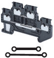 | 2 tiers, 1:1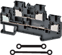 | 2 tiers, 1:1 | ||||
| Applicable wire sizes *1 | NOMINAL CROSS SECTION | 1.0 mm2 (1.25 mm2)*2 | 2.5 mm2 | 4.0 mm2 | |||
| Minimum conductor cross section solid | 0.14 mm2 | 0.14 mm2 | 0.2 mm2 | ||||
| Maximum conductor cross section solid | 1.5 mm2 | 4.0 mm2 | 6.0 mm2 | ||||
| Minimum conductor cross section fine stranded | 0.08 mm2 | 0.14 mm2 | 0.2 mm2 | ||||
| Maximum conductor cross section fine stranded | 1.5 mm2 | 2.5 mm2 | 4.0 mm2 | ||||
| Minimum conductor cross section (flex., stranded) with ferrule with Plastic sleeve | 0.14 mm2 | 0.14 mm2 | 0.25 mm2 | ||||
| Maximum conductor cross section (flex., stranded) with ferrule with Plastic sleeve | 1.0 mm2 (1.25 mm2)*2 | 2.5 mm2 | 4.0 mm2 | ||||
| Dimensions | 3.5 × 65.7 × 41.1 | 5.2 × 78.8 × 45.9 | 6.2 × 85 × 45.9 | ||||
| IEC rated voltage | 500 V | ||||||
| IEC rated current | 17.5 A/1.5 mm2 | 22 A/2.5 mm2 | 28 A/4.0 mm2 | ||||
| Usage Group (UG) | B, C | D | B, C | ||||
| UL rated voltage | 300 V | 51-150 V | 151-300 V | 301-600 V | 600 V | ||
| UL rated current | 15 A/ AWG14 (SOL) 10 A/ AWG16 | 15 A/ AWG14 (SOL) 10 A/ AWG16 | 10 A/ AWG16 | 5 A/ AWG16-20 | 20 A/AWG12 (SOL), 15 A/AWG14 | 30 A/AWG10 (SOL), 20 A/AWG12 | |
| Dielectric strength | 1,890 VAC for 1 min (leakage current: 1 mA max.) | 2,000 VAC for 1 min (leakage current: 1 mA max.) | |||||
| End Cover | XW5E-P1.5-1.1-2 | XW5E-P2.5-1.1-2 | XW5E-P4.0-1.1-2 | ||||
| Special tool | XW4Z-00B | ||||||
| Applicable nameplates | XW5Z-P1.5LB2 | XW5Z-P2.5LB[] or commercially available nameplate with 9.5 mm width and 0.5 mm thickness | XW5Z-P4.0LB[] or commercially available nameplate with 9.5 mm width and 0.5 mm thickness | ||||
| Applicable Short Bars | XW5S-P1.5-[] ([]: Poles = 2, 3, 4, 5 or 10) | XW5S-P2.5-[] ([]: Poles = 2, 3, 4, 5 or 10) | XW5S-P4.0-[] ([]: Poles = 2, 3, 4, 5 or 10) | ||||
*1. For the applicable wire ranges, refer to Data Sheet for solid and stranded wires and to for ferrules.
*2. You can also use 1.25 mm2 wires if you use 1.0 mm2 ferrules. However, if you do, care is required in the finished outer shape of the wires.
Feed Through Terminal blocks Multi conductor terminals
| Model | XW5T-P1.5-1.2-1 (BL) | XW5T-P2.5-1.2-1 (BL) | XW5T-P4.0-1.2-1 (BL) | ||||
|---|---|---|---|---|---|---|---|
| Appearance and internal wiring | 1 tier, 1:2 | 1 tier, 1:2 | 1 tier, 1:2 | ||||
| Applicable wire sizes *1 | NOMINAL CROSS SECTION | 1.0 mm2 (1.25 mm2)*2 | 2.5 mm2 | 4.0 mm2 | |||
| Minimum conductor cross section solid | 0.14 mm2 | 0.14 mm2 | 0.2 mm2 | ||||
| Maximum conductor cross section solid | 1.5 mm2 | 4.0 mm2 | 6.0 mm2 | ||||
| Minimum conductor cross section fine stranded | 0.08 mm2 | 0.14 mm2 | 0.2 mm2 | ||||
| Maximum conductor cross section fine stranded | 1.5 mm2 | 2.5 mm2 | 4.0 mm2 | ||||
| Minimum conductor cross section (flex., stranded) with ferrule with Plastic sleeve | 0.14 mm2 | 0.14 mm2 | 0.25 mm2 | ||||
| Maximum conductor cross section (flex., stranded) with ferrule with Plastic sleeve | 1.0 mm2 (1.25 mm2)*2 | 2.5 mm2 | 4.0 mm2 | ||||
| Dimensions | 3.5 × 54.1 × 30.5 | 5.2 × 60.5 × 35.3 | 6.2 × 66.5 × 35.3 | ||||
| IEC rated voltage | 500 V | 800 V | |||||
| IEC rated current | 17.5 A/1.5 mm2 | 24 A/2.5 mm2 | 32 A/4.0 mm2 | ||||
| Usage Group (UG) | B, C | D | B, C | ||||
| UL rated voltage | 300 V | 51-150 V | 151-300 V | 301-600 V | 600 V | ||
| UL rated current | 15 A/ AWG14 (SOL) 10 A/ AWG16 | 15 A/ AWG14 (SOL) 10 A/ AWG16 | 10 A/ AWG16 | 5 A/ AWG16-20 | 20 A/AWG12 (SOL), 15 A/AWG14 | 30 A/AWG10 (SOL), 20 A/AWG12 | |
| Dielectric strength | 1,890 VAC for 1 min (leakage current: 1 mA max.) | 2,000 VAC for 1 min (leakage current: 1 mA max.) | |||||
| End Cover | XW5E-P1.5-1.2-1 | XW5E-P2.5-1.2-1 | XW5E-P4.0-1.2-1 | ||||
| Special tool | XW4Z-00B | ||||||
| Applicable nameplates | XW5Z-P1.5LB[] or commercially available nameplate with 9.5 mm width and 0.5 mm thickness | XW5Z-P2.5LB[] or commercially available nameplate with 9.5 mm width and 0.5 mm thickness | XW5Z-P4.0LB[] or commercially available nameplate with 9.5 mm width and 0.5 mm thickness | ||||
| Applicable Short Bars | XW5S-P1.5-[] ([]: Poles = 2, 3, 4, 5 or 10) | XW5S-P2.5-[] ([]: Poles = 2, 3, 4, 5 or 10) | XW5S-P4.0-[] ([]: Poles = 2, 3, 4, 5 or 10) | ||||
| Model | XW5T-P1.5-2.2-1 (BL) | XW5T-P2.5-2.2-1 (BL) | XW5T-P4.0-2.2-1 (BL) | ||||
|---|---|---|---|---|---|---|---|
| Appearance and internal wiring | 1 tier, 2:2 | 1 tier, 2:2 | 1 tier, 2:2 | ||||
| Applicable wire sizes *1 | NOMINAL CROSS SECTION | 1.0 mm2 (1.25 mm2)*2 | 2.5 mm2 | 4.0 mm2 | |||
| Minimum conductor cross section solid | 0.14 mm2 | 0.14 mm2 | 0.2 mm2 | ||||
| Maximum conductor cross section solid | 1.5 mm2 | 4.0 mm2 | 6.0 mm2 | ||||
| Minimum conductor cross section fine stranded | 0.08 mm2 | 0.14 mm2 | 0.2 mm2 | ||||
| Maximum conductor cross section fine stranded | 1.5 mm2 | 2.5 mm2 | 4.0 mm2 | ||||
| Minimum conductor cross section (flex., stranded) with ferrule with Plastic sleeve | 0.14 mm2 | 0.14 mm2 | 0.25 mm2 | ||||
| Maximum conductor cross section (flex., stranded) with ferrule with Plastic sleeve | 1.0 mm2 (1.25 mm2)*2 | 2.5 mm2 | 4.0 mm2 | ||||
| Dimensions | 3.5 × 63.2 × 30.5 | 5.2 × 72.2 × 35.3 | 6.2 × 76.9 × 35.3 | ||||
| IEC rated voltage | 500 V | 800 V | |||||
| IEC rated current | 17.5 A/1.5 mm2 | 24 A/2.5 mm2 | 32 A/4.0 mm2 | ||||
| Usage Group (UG) | B, C | D | B, C | ||||
| UL rated voltage | 300 V | 51-150 V | 151-300 V | 301-600 V | 600 V | ||
| UL rated current | 15 A/ AWG14 (SOL) 10 A/ AWG16 | 15 A/ AWG14 (SOL) 10 A/ AWG16 | 10 A/ AWG16 | 5 A/ AWG16-20 | 20 A/AWG12 (SOL), 15 A/AWG14 | 30 A/AWG10 (SOL), 20 A/AWG12 | |
| Dielectric strength | 1,890 VAC for 1 min (leakage current: 1 mA max.) | 2,000 VAC for 1 min (leakage current: 1 mA max.) | |||||
| End Cover | XW5E-P1.5-2.2-1 | XW5E-P2.5-2.2-1 | XW5E-P4.0-2.2-1 | ||||
| Special tool | XW4Z-00B | ||||||
| Applicable nameplates | XW5Z-P1.5LB[] or commercially available nameplate with 9.5 mm width and 0.5 mm thickness | XW5Z-P2.5LB[] or commercially available nameplate with 9.5 mm width and 0.5 mm thickness | XW5Z-P4.0LB[] or commercially available nameplate with 9.5 mm width and 0.5 mm thickness | ||||
| Applicable Short Bars | XW5S-P1.5-[] ([]: Poles = 2, 3, 4, 5 or 10) | XW5S-P2.5-[] ([]: Poles = 2, 3, 4, 5 or 10) | XW5S-P4.0-[] ([]: Poles = 2, 3, 4, 5 or 10) | ||||
*1. For the applicable wire ranges, refer to Data Sheet for solid and stranded wires and to for ferrules.
*2. You can also use 1.25 mm2 wires if you use 1.0 mm2 ferrules. However, if you do, care is required in the finished outer shape of the wires.
Grounding Terminal blocks Standard terminals
| Model | XW5G-P1.5-1.1-1 | XW5G-P2.5-1.1-1 | XW5G-P4.0-1.1-1 | |
|---|---|---|---|---|
| Appearance and internal wiring | 1 tier, 1:1 | 1 tier, 1:1 | 1 tier, 1:1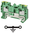 | |
| Applicable wire sizes *1 | NOMINAL CROSS SECTION | 1.0 mm2 (1.25 mm2)*2 | 2.5 mm2 | 4 mm2 |
| Minimum conductor cross section solid | 0.14 mm2 | 0.14 mm2 | 0.2 mm2 | |
| Maximum conductor cross section solid | 1.5 mm2 | 4.0 mm2 | 6.0 mm2 | |
| Minimum conductor cross section fine stranded | 0.08 mm2 | 0.14 mm2 | 0.2 mm2 | |
| Maximum conductor cross section fine stranded | 1.5 mm2 | 2.5 mm2 | 4.0 mm2 | |
| Minimum conductor cross section (flex., stranded) with ferrule with Plastic sleeve | 0.14 mm2 | 0.14 mm2 | 0.25 mm2 | |
| Maximum conductor cross section (flex., stranded) with ferrule with Plastic sleeve | 1.0 mm2 (1.25 mm2)*2 | 2.5 mm2 | 4.0 mm2 | |
| Dimensions | 3.5 × 45 × 30.5 | 5.2 × 48.8 × 35.3 | 6.2 × 56.1 × 35.3 | |
| IEC rated voltage | 500 V | 800 V | ||
| UL rated voltage | 600 V | |||
| Dielectric strength | 1,890 VAC for 1 min (leakage current: 1 mA max.) | 2,000 VAC for 1 min (leakage current: 1 mA max.) | ||
| End Cover | XW5E-P1.5-1.1-1 | XW5E-P2.5-1.1-1 | XW5E-P4.0-1.1-1 | |
| Special tool | XW4Z-00B | |||
| Applicable nameplates | XW5Z-P1.5LB[] or commercially available nameplate with 9.5 mm width and 0.5 mm thickness | XW5Z-P2.5LB[] or commercially available nameplate with 9.5 mm width and 0.5 mm thickness | XW5Z-P4.0LB[] or commercially available nameplate with 9.5 mm width and 0.5 mm thickness | |
| Applicable Short Bars | XW5S-P1.5-[] ([]: Poles = 2, 3, 4, 5 or 10) | XW5S-P2.5-[] ([]: Poles = 2, 3, 4, 5 or 10) | XW5S-P4.0-[] ([]: Poles = 2, 3, 4, 5 or 10) | |
Note: If you use a Grounding Terminal Block, use a DIN Track for grounding.
*1. For the applicable wire ranges, refer to Data Sheet for solid and stranded wires and to for ferrules.
*2. You can also use 1.25 mm2 wires if you use 1.0 mm2 ferrules. However, if you do, care is required in the finished outer shape of the wires.
Grounding Terminal blocks Multi tiers terminal
| Model | XW5G-P1.5-1.1-2 | XW5G-P2.5-1.1-2 | XW5G-P4.0-1.1-2 | |
|---|---|---|---|---|
| Appearance and internal wiring | 2 tier, 1:1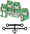 | 2 tiers, 1:1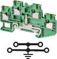 | 2 tiers, 1:1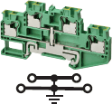 | |
| Applicable wire sizes *1 | NOMINAL CROSS SECTION | 1.0 mm2 (1.25 mm2)*2 | 2.5 mm2 | 4.0 mm2 |
| Minimum conductor cross section solid | 0.14 mm2 | 0.14 mm2 | 0.2 mm2 | |
| Maximum conductor cross section solid | 1.5 mm2 | 4.0 mm2 | 6.0 mm2 | |
| Minimum conductor cross section fine stranded | 0.08 mm2 | 0.14 mm2 | 0.2 mm2 | |
| Maximum conductor cross section fine stranded | 1.5 mm2 | 2.5 mm2 | 4.0 mm2 | |
| Minimum conductor cross section (flex., stranded) with ferrule with Plastic sleeve | 0.14 mm2 | 0.14 mm2 | 0.25 mm2 | |
| Maximum conductor cross section (flex., stranded) with ferrule with Plastic sleeve | 1.0 mm2 (1.25 mm2)*2 | 2.5 mm2 | 4.0 mm2 | |
| Dimensions | 3.5 × 65.7 × 41.1 | 5.2 × 78.8 × 45.9 | 6.2 × 85 × 45.9 | |
| IEC rated voltage | 500 V | |||
| UL rated voltage | 600 V | |||
| Dielectric strength | 1,890 VAC for 1 min (leakage current: 1 mA max.) | 2,000 VAC for 1 min (leakage current: 1 mA max.) | ||
| End Cover | XW5E-P1.5-1.1-2 | XW5E-P2.5-1.1-2 | XW5E-P4.0-1.1-2 | |
| Special tool | XW4Z-00B | |||
| Applicable nameplates | XW5Z-P1.5LB2 | XW5Z-P2.5LB[] or commercially available nameplate with 9.5 mm width and 0.5 mm thickness | XW5Z-P4.0LB[] or commercially available nameplate with 9.5 mm width and 0.5 mm thickness | |
| Applicable Short Bars | XW5S-P1.5-[] ([]: Poles = 2, 3, 4, 5 or 10) | XW5S-P2.5-[] ([]: Poles = 2, 3, 4, 5 or 10) | XW5S-P4.0-[] ([]: Poles = 2, 3, 4, 5 or 10) | |
Note: If you use a Grounding Terminal Block, use a DIN Track for grounding.
*1. For the applicable wire ranges, refer to Data Sheet for solid and stranded wires and to for ferrules.
*2. You can also use 1.25 mm2 wires if you use 1.0 mm2 ferrules. However, if you do, care is required in the finished outer shape of the wires.
Grounding Terminal blocks Multi conductor terminals
| Model | XW5G-P1.5-1.2-1 | XW5G-P2.5-1.2-1 | XW5G-P4.0-1.2-1 | |
|---|---|---|---|---|
| Appearance and internal wiring | 1 tier, 1:2 | 1 tier, 1:2 | 1 tier, 1:2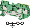 | |
| Applicable wire sizes *1 | NOMINAL CROSS SECTION | 1.0 mm2 (1.25 mm2)*2 | 2.5 mm2 | 4.0 mm2 |
| Minimum conductor cross section solid | 0.14 mm2 | 0.14 mm2 | 0.2 mm2 | |
| Maximum conductor cross section solid | 1.5 mm2 | 4.0 mm2 | 6.0 mm2 | |
| Minimum conductor cross section fine stranded | 0.08 mm2 | 0.14 mm2 | 0.2 mm2 | |
| Maximum conductor cross section fine stranded | 1.5 mm2 | 2.5 mm2 | 4.0 mm2 | |
| Minimum conductor cross section (flex., stranded) with ferrule with Plastic sleeve | 0.14 mm2 | 0.14 mm2 | 0.25 mm2 | |
| Maximum conductor cross section (flex., stranded) with ferrule with Plastic sleeve | 1.0 mm2 (1.25 mm2)*2 | 2.5 mm2 | 4.0 mm2 | |
| Dimensions | 3.5 × 54.1 × 30.5 | 5.2 × 60.5 × 35.3 | 6.2 × 66.5 × 35.3 | |
| IEC rated voltage | 500 V | 800 V | ||
| UL rated voltage | 600 V | 600 V | ||
| Dielectric strength | 1,890 VAC for 1 min (leakage current: 1 mA max.) | 2,000 VAC for 1 min (leakage current: 1 mA max.) | ||
| End Cover | XW5E-P1.5-1.2-1 | XW5E-P2.5-1.2-1 | XW5E-P4.0-1.2-1 | |
| Special tool | XW4Z-00B | |||
| Applicable nameplates | XW5Z-P1.5LB[] or commercially available nameplate with 9.5 mm width and 0.5 mm thickness | XW5Z-P2.5LB[] or commercially available nameplate with 9.5 mm width and 0.5 mm thickness | XW5Z-P4.0LB[] or commercially available nameplate with 9.5 mm width and 0.5 mm thickness | |
| Applicable Short Bars | XW5S-P1.5-[] ([]: Poles = 2, 3, 4, 5 or 10) | XW5S-P2.5-[] ([]: Poles = 2, 3, 4, 5 or 10) | XW5S-P4.0-[] ([]: Poles = 2, 3, 4, 5 or 10) | |
| Model | XW5G-P1.5-2.2-1 | XW5G-P2.5-2.2-1 | XW5G-P4.0-2.2-1 | |
|---|---|---|---|---|
| Appearance and internal wiring | 1 tier, 2:2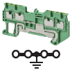 | 1 tier, 2:2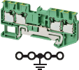 | 1 tier, 2:2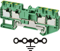 | |
| Applicable wire sizes *1 | NOMINAL CROSS SECTION | 1.0 mm2 (1.25 mm2)*2 | 2.5 mm2 | 4.0 mm2 |
| Minimum conductor cross section solid | 0.14 mm2 | 0.14 mm2 | 0.2 mm2 | |
| Maximum conductor cross section solid | 1.5 mm2 | 4.0 mm2 | 6.0 mm2 | |
| Minimum conductor cross section fine stranded | 0.08 mm2 | 0.14 mm2 | 0.2 mm2 | |
| Maximum conductor cross section fine stranded | 1.5 mm2 | 2.5 mm2 | 4.0 mm2 | |
| Minimum conductor cross section (flex., stranded) with ferrule with Plastic sleeve | 0.14 mm2 | 0.14 mm2 | 0.25 mm2 | |
| Maximum conductor cross section (flex., stranded) with ferrule with Plastic sleeve | 1.0 mm2 (1.25 mm2)*2 | 2.5 mm2 | 4.0 mm2 | |
| Dimensions | 3.5 × 63.2 × 30.5 | 5.2 × 72.2 × 35.3 | 6.2 × 76.9 × 35.3 | |
| IEC rated voltage | 500 V | 800 V | ||
| UL rated voltage | 600 V | |||
| Dielectric strength | 1,890 VAC for 1 min (leakage current: 1 mA max.) | 2,000 VAC for 1 min (leakage current: 1 mA max.) | ||
| End Cover | XW5E-P1.5-2.2-1 | XW5E-P2.5-2.2-1 | XW5E-P4.0-2.2-1 | |
| Special tool | XW4Z-00B | |||
| Applicable nameplates | XW5Z-P1.5LB[] or commercially available nameplate with 9.5 mm width and 0.5 mm thickness | XW5Z-P2.5LB[] or commercially available nameplate with 9.5 mm width and 0.5 mm thickness | XW5Z-P4.0LB[] or commercially available nameplate with 9.5 mm width and 0.5 mm thickness | |
| Applicable Short Bars | XW5S-P1.5-[] ([]: Poles = 2, 3, 4, 5 or 10) | XW5S-P2.5-[] ([]: Poles = 2, 3, 4, 5 or 10) | XW5S-P4.0-[] ([]: Poles = 2, 3, 4, 5 or 10) | |
Note: If you use a Grounding Terminal Block, use a DIN Track for grounding.
*1. For the applicable wire ranges, refer to Data Sheet for solid and stranded wires and to for ferrules.
*2. You can also use 1.25 mm2 wires if you use 1.0 mm2 ferrules. However, if you do, care is required in the finished outer shape of the wires.
Performance
| Operating temperature | -40 to 55°C (with no condensation or icing) |
|---|---|
| Operating humidity | 5% to 95% |
| Insulating material | PA resin |
| Fire resistance | UL94 V-0 |
| Insertion durability | 50 times |
| Vibration resistance | 10 to 150 Hz, Acceleration of 50 m/s2 for 80 min each in X, Y, and Z directions |
| Shock resistance | 500 m/s2 for 11 ms each in 6 directions 5 times |
| Storage Temperature Range | -40 to 85°C (with no condensation or icing) |
| Storage Humidity Range | 5% to 95% |
Short Bars
| Model | XW5S-P1.5-[] | XW5S-P2.5-[] | XW5S-P4.0-[] |
|---|---|---|---|
| Rated voltage | 500 V | 800 V | |
| Rated current | 17.5 A | 24 A | 32 A |
Certification
Applicable Safety Standards
cURus (UL 1059/CSA C22.2 No. 158)
Certification
cURus (file No. E245101)
last update: April 3, 2017
OMRON XW5T-P catalog
XW5T-P DIN Track Push-in Terminal Blocks/Catalog- Catalog
- CAD
English
Global Edition
| Catalog Name | Catalog Number [size] | Last Update | |
|---|---|---|---|
| | G123-E1-02 [5452KB] | May 07, 201820180507 | XW5T Catalog |
| | G124-E1-03 [6231KB] | Jan 07, 201920190107 | XW5T DIN Track Push-in Terminal Blocks Data Sheet |
| | G125-E1-02 [6260KB] | Dec 14, 201720171214 | XW5T DIN Track Terminal Blocks with Screw Terminals Data Sheet |
OMRON XW5T-P dimension
XW5T-P DIN Track Push-in Terminal Blocks/Dimensionslast update: April 3, 2017
(Unit: mm)
DIN Track Terminal Blocks
XW5T-P1.5-1.1-1 (BL)/XW5G-P1.5-1.1-1
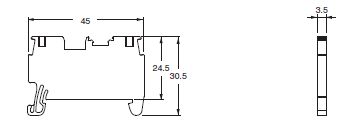
XW5T-P1.5-1.2-1 (BL)/XW5G-P1.5-1.2-1
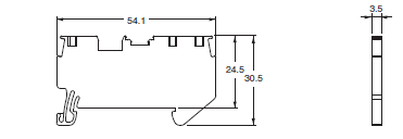
XW5T-P1.5-2.2-1 (BL)/XW5G-P1.5-2.2-1
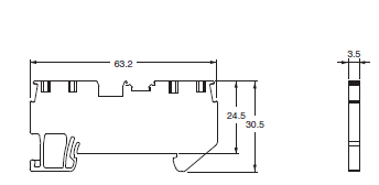
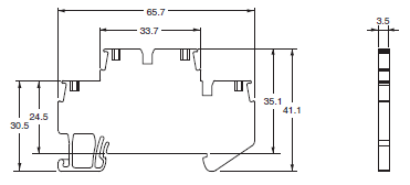
XW5T-P1.5-1.1-2 (BL)/XW5G-P1.5-1.1-2
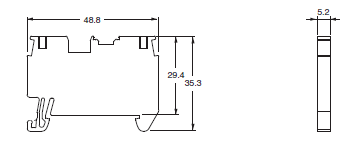
XW5T-P2.5-1.1-1 (BL)/XW5G-P2.5-1.1-1
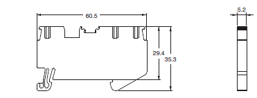
XW5T-P2.5-1.2-1 (BL)/XW5G-P2.5-1.2-1
XW5T-P2.5-2.2-1 (BL)/XW5G-P2.5-2.2-1
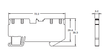
XW5T-P2.5-1.1-2 (BL)/XW5G-P2.5-1.1-2
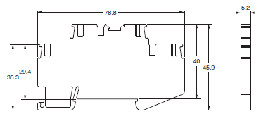
XW5T-P4.0-1.1-1 (BL)/XW5G-P4.0-1.1-1
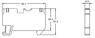
XW5T-P4.0-1.2-1 (BL)/XW5G-P4.0-1.2-1
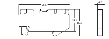
XW5T-P4.0-2.2-1 (BL)/XW5G-P4.0-2.2-1
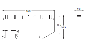
XW5T-P4.0-1.1-2 (BL)/XW5G-P4.0-1.1-2
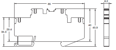
Short Bars
XW5S-P1.5-[]

XW5S-P2.5-[]

XW5S-P4.0-[]

End Cover
XW5E-P1.5-1.1-1
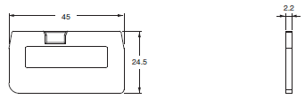
XW5E-P1.5-1.2-1
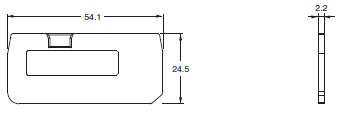
XW5E-P1.5-2.2-1
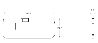
XW5E-P1.5-1.1-2
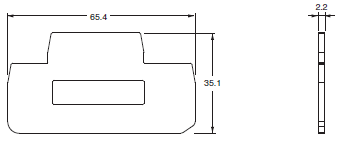
XW5E-P2.5-1.1-1
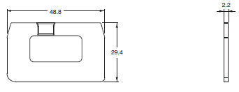
XW5E-P2.5-1.2-1
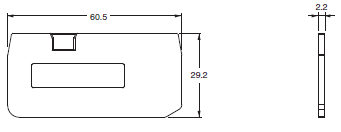
XW5E-P2.5-2.2-1
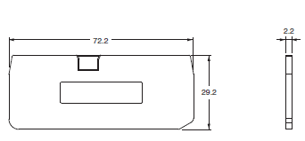
XW5E-P2.5-1.1-2
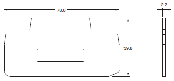
XW5E-P4.0-1.1-1

XW5E-P4.0-1.2-1
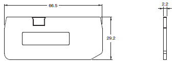
XW5E-P4.0-2.2-1
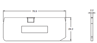
XW5E-P4.0-1.1-2
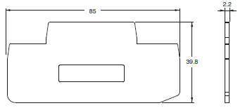
End Brackets/Separator Plates
XW5Z-EP6 (End Brackets)
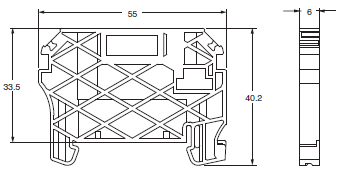
XW5Z-EP12 (Separator Plates)
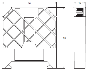
last update: April 3, 2017
- NO. XW5T-P
- TYPE:Wiring Systems DIN Track Terminal Blocks
 Copyright Statement
 - DATE:2021-06-09
- Associated products:
XW2Z-[][][]P-V / S-V / S-CV / T Host Link Cables (RS-232C Cables for Programmable Controller)/Features XW5T-S DIN Track Terminal Blocks with Screw Terminals/Features