OMRON E3S-CSensors/ Photoelectric Sensors/Built-in Amplifier
OMRON E3S-C Sensors
- E3S-C Oil-resistive, Long-range Photoelectric Sensor with Metal Housing/Specifications
- E3S-C Oil-resistive, Long-range Photoelectric Sensor with Metal Housing/Dimensions
- E3S-C Oil-resistive, Long-range Photoelectric Sensor with Metal Housing/Catalog
- E3S-C Oil-resistive, Long-range Photoelectric Sensor with Metal Housing/Lineup
- Purchase the OMRON E3S-C Built-in Amplifier
OMRON E3S-C Dimensions
/Images/l_412-25-118730-198x198.jpglast update: December 19, 2013
• Excellent resistance against the water and oil. Easy application in locations with oil mist.
• Long-range sensing up to 30 m with Through-beam models.
• Shock resistance rated at 1,000m/s2.
• Product lineup includes metal M12 pre-wired connector models.
• NPN/PNP selector switch output.
last update: December 19, 2013
Purchase the OMRON Built-in Amplifier Please fill in the following
If you have just landed here, this product OMRON E3S-C Sensors,Sensors is offered online by Tianin FLD Technical Co.,Ltd. This is an online store providing Sensors at wholesale prices for consumers. You can call us or send enquiry, we would give you the prices, packing,deliverty and more detailed information on the E3S-C We cooperate with DHL,TNT,FEDEX,UPS,EMS,etc.They guarantee to meet your needs in terms of time and money,even if you need your OMRON E3S-CSensors tomorrow morning (aka overnight or next day air) on your desk, 2, 3 days or more.Note to international customers, YES, we ship worldwide.
D4N Safety Limit Switch/Features
A165E Emergency Stop Switch (16-dia.)/Features
F3W-E Picking Sensor/Features
M2BJ Buzzer (Cylindrical 16-dia.)/Features
XW3B Connector Terminal Boxes/Features
OMRON E3S-C specification
E3S-C Oil-resistive, Long-range Photoelectric Sensor with Metal Housing/Specificationslast update: September 24, 2012
Ratings and Specifications
| Sensing method | Through-beam | Retro-reflective (with M.S.R. function) *1 | Diffuse reflective | ||
|---|---|---|---|---|---|
| Model | Horizontal E3S-CT11(-M1J) | Horizontal E3S-CR 11(-M1J) | Horizontal E3S-CD11(-M1J) | Horizontal E3S-CD12(-M1J) | |
| Vertical E3S-CT61(-M1J) | Vertical E3S-CR 61(-M1J) | Vertical E3S-CD61(-M1J) | Vertical E3S-CD62(-M1J) | ||
| Sensing distance | 30 m | 3 m (when using E39-R1) | 700 mm (300 × 300 mm white paper) | 2 m (300 × 300 mm white paper) | |
| Standard sensing object | Opaque, 15-mm dia. min. | Opaque, 75-mm dia. min. | --- | ||
| Differential travel | --- | 20% max. of sensing distance | |||
| Directional angle | Emitter and Receiver: 3° to15° | 3° to 10° | --- | ||
| Light source (wavelength) | Infrared LED (880 nm) | Red LED (700 nm) | Infrared LED (880 nm) | ||
| Power supply voltage | 10 to 30 VDC including 10% (p.p) ripple | ||||
| Current consumption | 50 mA max. (Emitter 25 mA max. Receiver 25 mA max.) | 40 mA max. | |||
| Control output | Load power supply voltage: 30 VDC max. Load current: 100 mA max. (Residual voltage: NPN output: 1.2 V max., PNP output: 2.0 V max.) Open controller output (NPN/PNP selectable) Light-ON/Dark-ON selectable | ||||
| Protection circuits | Power supply reverse polarity circuit protection, Output short- circuit protection | Power supply reverse polarity protection, Output short-circuit protection, Mutual interference prevention | |||
| Response time | Operate or reset: 1 ms max. | Operate or reset 2 ms max. | |||
| Sensitivity adjustment | One-turn adjuster | Two-turn endless adjuster with an indicator | |||
| Ambient illumination (Receiver side) | Incandescent lamp: 5,000 lx max. Sunlight: 10,000 lx max. | ||||
| Ambient temperature range | Operating: -25°C to 55°C, Storage: -40°C to 70°C (with no icing or condensation) | ||||
| Ambient humidity range | Operating: 35% to 85%, Storage: 35% to 95% (with no condensation) | ||||
| Insulation resistance | 20 MΩ min. (at 500 VDC) | ||||
| Dielectric strength | 1,000 VAC, 50/60 Hz for 1 min | ||||
| Vibration resistance | Destruction: 10 to 2,000 Hz, 1.5-mm double amplitude or 300 m/s2 for 0.5 hours each in X, Y, and Z directions | ||||
| Shock resistance | Destruction: 1,000 m/s2 3 times each in X, Y, and Z directions | ||||
| Degree of protection | IEC60529: IP67 (in-house standards: oil-resistant), NEMA: 6P (indoors only) *2 | ||||
| Connection method | Pre-wired (standard cable length: 2 m) or Pre-wired M12 Connector (standard cable length: 0.3 m) | ||||
| Weight (packed state) | Approx. 270 g (Pre-wired cable) Approx. 230 g (Pre-wired Connector (M12)) | Approx. 160 g (Pre-wired cable) Approx. 130 g (Pre-wired Connector (M12)) | Approx. 150 g (Pre-wired cable) Approx. 110 g (Pre-wired Connector (M12)) | ||
| Material | Case | Zinc die-cast | |||
| Operation panel cover | PES (polyether sulfone) | ||||
| Lens | Methacrylic resin | ||||
| Mounting Bracket | Stainless steel (SUS304) | ||||
| Accessories | Mounting Bracket (with screws), Adjustment screwdriver, Instruction manual, and Reflector (only for Retro-reflective Sensors) | ||||
Note:Refer to MSR function of Technical Guide.
Note:NEMA: National Electrical Manufactures Association
last update: September 24, 2012
OMRON E3S-C dimension
E3S-C Oil-resistive, Long-range Photoelectric Sensor with Metal Housing/Dimensionslast update: September 24, 2012
Note:Tolerance class IT16 applies to dimensions in this datasheet unless otherwise specified.
Sensors
Through-beam (Horizontal)
E3S-CT11(-M1J)
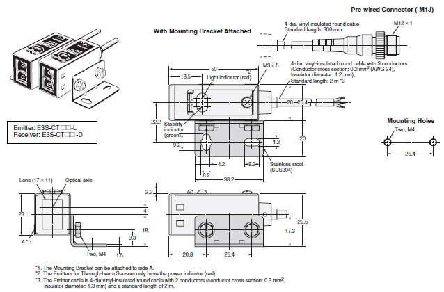
Note:Models numbers for Through-beam Sensors (E3S-CT11(-M1J)) are for sets that include both the Emitter and Receiver.
The model number of the Emitter is expressed by adding "-L" to the set model number (example: E3S-CT11-L 2M), the model number of the Receiver, by adding "-D" (example: E3S-CT11-D 2M.) Refer to Lineup to confirm model numbers for Emitter and Receivers.
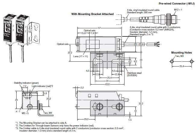
Through-beam (Vertical)
E3S-CT61(-MJ)
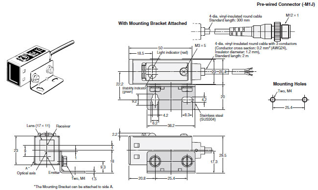
Retro-/Diffuse-reflective (Horizontal)
E3S-CR11(-M1J)
E3S-CD11(-M1J)
E3S-CD12(-M1J)
Note:Models numbers for Through-beam Sensors (E3S-CT61(-M1J)) are for sets that include both the Emitter and Receiver.
The model number of the Emitter is expressed by adding "-L" to the set model number (example: E3S-CT61-L 2M), the model number of the Receiver, by adding "-D" (example: E3S-CT61-D 2M.) Refer to Ordering Information to confirm model numbers for Emitter and Receivers.
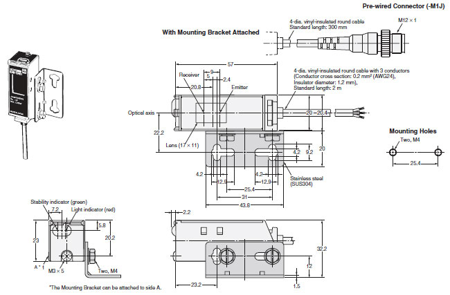
Retro-/Diffuse-reflective (Vertical)
E3S-CR61(-M1J)
E3S-CD61(-M1J)
E3S-CD62(-M1J)
Accessories (Order Separately)
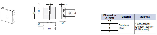
Snap-in Long Slit (For Through-beam Models)
E39-S61
last update: September 24, 2012
OMRON E3S-C catalog
E3S-C Oil-resistive, Long-range Photoelectric Sensor with Metal Housing/Catalog- Catalog
- Manual
- CAD
English
Global Edition
| Catalog Name | Catalog Number [size] | Last Update | |
|---|---|---|---|
| | - [1180KB] | Apr 09, 201520150409 | E3S-C Data Sheet |
| | - [438KB] | Jun 01, 201720170601 | E3S-C Operating Procedures |
OMRON E3S-C lineup
E3S-C Oil-resistive, Long-range Photoelectric Sensor with Metal Housing/Lineuplast update: April 09, 2015
Sensors
| Sensing method | Appearance | Connection method | Sensing distance | Model |
|---|---|---|---|---|
| Through-beam (Emitter + Receiver) * | Horizontal | Pre-wired | 30 m (Infrared light) | E3S-CT11 2M Emitter E3S-CT11-L 2M Receiver E3S-CT11-D 2M |
| Pre-wired Connector (M12) | E3S-CT11-M1J 0.3M Emitter E3S-CT11-L-M1J 0.3M Receiver E3S-CT11-D-M1J 0.3M | |||
Vertical | Pre-wired | E3S-CT61 2M Emitter E3S-CT61-L 2M Receiver E3S-CT61-D 2M | ||
| Pre-wired Connector (M12) | E3S-CT61-M1J 0.3M Emitter E3S-CT61-L-M1J 0.3M Receiver E3S-CT61-D-M1J 0.3M | |||
| Retro-reflective | Horizontal | Pre-wired | 3 m (Red light) | E3S-CR11 2M |
| Pre-wired Connector (M12) | E3S-CR11-M1J 0.3M | |||
Vertical | Pre-wired | E3S-CR61 2M | ||
| Pre-wired Connector (M12) | E3S-CR61-M1J 0.3M | |||
| Diffuse-reflective | Horizontal | Pre-wired | 700 mm (Infrared light) | E3S-CD11 2M |
| 2 m (Infrared light) | E3S-CD12 2M | |||
| Pre-wired Connector (M12) | 700 mm (Infrared light) | E3S-CD11-M1J 0.3M | ||
| 2 m (Infrared light) | E3S-CD12-M1J 0.3M | |||
Vertical | Pre-wired | 700 mm (Infrared light) | E3S-CD61 2M | |
| 2 m (Infrared light) | E3S-CD62 2M | |||
| Pre-wired Connector (M12) | 700 mm (Infrared light) | E3S-CD61-M1J 0.3M | ||
| 2 m (Infrared light) | E3S-CD62-M1J 0.3M |
* Through-beam Sensors are normally sold in sets that include both the Emitter and Receiver.
Accessories (Order Separately)
Slits
(A Slit is not provided with Through-beam Sensors. Order a Slit separately if required.)
| Slit width | Sensing distance | Minimum detectable object (reference value) | Model | Quantity | Remarks |
|---|---|---|---|---|---|
| 0.5 mm × 11 mm | 1.8 m | 0.5-mm dia. | E39-S61 | 1 set each for Emitter and Receiver (8 Slits total) | (Snap-in Long Slit) Can be used with the E3S-CT[]1(-M1J) Through-beam Sensor. Refer to Data Sheet. |
| 1 mm × 11 mm | 3.5 m | 1-mm dia. | |||
| 2 mm × 11 mm | 7 m | 2-mm dia. | |||
| 4 mm × 11 mm | 15 m | 2.6-mm dia. |
Reflectors
(A Reflector is required for each Retro-reflective Sensor)
The E39-R1 Reflector is provided with the Sensor. Order other Reflectors separately if required.
| Name | Sensing distance | Model | Quantity | Remarks | |
|---|---|---|---|---|---|
| Rated value | Reference value | ||||
| Reflectors | 3 m | --- | E39-R1 | 1 | Provided with the E3S-CR[]1(-M1J) Retro-reflective Sensor. |
| --- | 4 m | E39-R2 | 1 | --- | |
| Small Reflectors | --- | 1.5 m | E39-R3 | 1 | --- |
| --- | 750 mm | E39-R4 | 1 | --- | |
| Tape Reflectors | --- | 700 mm (50 mm) * | E39-RS1 | 1 | Enables MSR function. |
| --- | 1,100 mm (100 mm) * | E39-RS2 | 1 | ||
| --- | 1,400 mm (100 mm) * | E39-RS3 | 1 | ||
Note: 1. If you use any Reflector other than the enclosed Reflector, make sure that the stability indicator lights properly
when you set the Sensor.
2. Refer to Reflectors on E39-L/E39-S/E39-R for details.
* Values in parentheses indicate the minimum distance required between the Sensor and Reflector.
Mounting Brackets
Some Mounting Brackets are provided with the Sensor. Order other Mounting Brackets separately if required.
| Appearance | Model | Quantity | Remarks |
|---|---|---|---|
 | E39-L102 | 1 | Provided with Horizontal Models. |
 | E39-L103 | 1 | Provided with Vertical Models. |
 | E39-L85 | 1 | Mounting bracket for changing from E3S-[][][][][]42/44 to E3S-C Vertical Models. |
 | E39-L86 | 1 | Mounting bracket for changing from E3S-[][][][][]43 to E3S-C Vertical Models. |
 | E39-L87 | 1 | --- |
Note: 1. When using a Through-beam Sensor, order one Connector for the Receiver and one for the Emitter.
2. Refer to Mounting Brackets on E39-L/F39-L/E39-S/E39-R for details.
Sensor I/O Connectors (Sockets on One Cable End)
(Models with Pre-wired Connectors: A Connector is not provided with the Sensor. Be sure to order a Connector separately.)
| Cable | Appearance | Cable type | Model | |
|---|---|---|---|---|
| Fire-retardant, robot cable |  | 2 m | 3-wire | XS2F-D421-DC0-F |
| 5 m | XS2F-D421-GC0-F | |||
 | 2 m | XS2F-D422-DC0-F | ||
| 5 m | XS2F-D422-GC0-F | |||
Note: 1. When using a Through-beam Sensor, order one Connector for the Receiver and one for the Emitter.
2. For details on Sensor I/O Connectors and cables such as vibration-proof robot cables, refer to Introduction to
Sensor I/O Connectors/Sensor Controllers.
last update: April 09, 2015
- NO. E3S-C
- TYPE:Photoelectric Sensors Built-in Amplifier
 Copyright Statement
 - DATE:2021-06-16
- Associated products:
E3Z-G Grooved-type Photoelectric Sensor with Built-in Amplifier/Features E3S-CL Distance-settable Photoelectric Sensor with Metal Case/Features