OMRON MMRelays/ General Purpose Relays/For Control Panel
OMRON MM Relays
OMRON MM Dimensions
/Images/l_959-25-118983-198x198.jpglast update: December 19, 2013
• Easy to mount, wire, and use.
• A large selection of models including various contact forms, DC-switching models, and open models.
• Mechanical life: 5,000,000 operations; electrical life (under rated load): 500,000 operations.
• Models also available with built-in diodes and for use as auxiliary power relays.
last update: December 19, 2013
Purchase the OMRON For Control Panel Please fill in the following
If you have just landed here, this product OMRON MM Relays,Relays is offered online by Tianin FLD Technical Co.,Ltd. This is an online store providing Relays at wholesale prices for consumers. You can call us or send enquiry, we would give you the prices, packing,deliverty and more detailed information on the MM We cooperate with DHL,TNT,FEDEX,UPS,EMS,etc.They guarantee to meet your needs in terms of time and money,even if you need your OMRON MMRelays tomorrow morning (aka overnight or next day air) on your desk, 2, 3 days or more.Note to international customers, YES, we ship worldwide.
F3SP-T01 Safety Terminal Relays (for F3SJ-A[][][][]P[][])/Features
D40Z Compact non-contact Door Switch/Features
W4S1 Industrial Switching Hubs/Features
CJ1W-MD CJ-series Mixed I/O Units/Features
CRT1-[]D08(-1) / []D16(-1) / ROS[] / ROF[] Digital I/O Slave Units with Screw Terminal Blocks (2-...
OMRON MM specification
MM Power Relay/Specificationslast update: October 14, 2014
Coil Ratings
Open Coils (with Solder or Screw Terminals)
| Rated voltage (V) | Rated current (mA) | Coil resistance (Ω) | Must- operate voltage | Must- release voltage | Max. volt- age | Power consumption (VA or W) | ||||||
|---|---|---|---|---|---|---|---|---|---|---|---|---|
| DP | 3P or 4P | DP | 3P or 4P | |||||||||
| 50 Hz | 60 Hz | 50 Hz | 60 Hz | % of rated voltage | Initial | Rated | ||||||
| AC | 6 | 790 | 655 | 1,120 | 950 | 1.1 | 0.5 | 80% max. | 30% min. (60 Hz) 25% min. (50 Hz) | 110% | Approx. 4.1 (DP) Approx. 6.3 (3P or 4P) | Approx. 3.5 (DP) Approx. 5.1 (3P or 4P) |
| 12 | 395 | 325 | 560 | 480 | 4.7 | 2.0 | ||||||
| 24 | 195 | 160 | 280 | 240 | 19 | 8.5 | ||||||
| 50 | 94 | 78 | 134 | 114 | 82 | 36 | ||||||
| 100/(110) | 47 | 39/45 | 67 | 57/66 | 340 | 150 | ||||||
| 200/(220) | 23.5 | 19.5/22.5 | 33.5 | 28.5/33 | 1,540 | 620 | ||||||
| DC | 6 | 340 | 450 | 17.5 | 13.4 | 70% max. | 10% min. | Approx. 2.1 (DP) Approx. 2.7 (3P or 4P) | ||||
| 12 | 176 | 220 | 68 | 54 | ||||||||
| 24 | 87 | 94 | 275 | 255 | ||||||||
| 48 | 41 | 52 | 1,180 | 930 | ||||||||
| 100/110 | 17/19 | 22/24.5 | 5,750 | 4,500 | ||||||||
| 200/220 | 8.6/9.5 | 11/12 | 23,200 | 18,000 | ||||||||
Note: 1. The rated current and coil resistance are measured at a coil temperature of 23°C with tolerances of +15%/-20%
for AC rated current and ±15% for DC coil resistance.
2. The AC coil resistance values are reference values.
3. Performance characteristic data are measured at a coil temperature of 23°C.
4. The maximum voltage is one that is applicable instantaneously to the Relay coil at an ambient temperature of
23°C and not continuously.
Cased Coils (Plug-in Terminals)
The rated current may vary if the Relay has a built-in operating indicator (See note 4.).
| Rated voltage (V) | Rated current (mA) | Coil resistance (Ω) | Coil inductance (H) | Must- oper- ate volt- age | Must- re- lease volt- age | Max. volt- age | Power con- sumption (VA or W) | |||||||||
|---|---|---|---|---|---|---|---|---|---|---|---|---|---|---|---|---|
| DP | 3P or 4P | DP | 3P or 4P | DP | 3P or 4P | |||||||||||
| 50 Hz | 60 Hz | 50 Hz | 60 Hz | Con- tact re- lease | Con- tact oper- ate | Con- tact re- lease | Con- tact oper- ate | % of rated voltage | Ini- tial | Rated | ||||||
| AC | 6 | 690 | 590 | 975 | 850 | 1.1 | 0.5 | 0.02 | 0.02 | 0.01 | 0.03 | 80% max. | 30% min. (60 Hz) 25% min. (50 Hz) | 110% | Ap- prox. 4.1 (DP) Ap- prox. 6.3 (3P or 4P) | Ap- prox. 3.5 (DP) Ap- prox. 5.1 (3P or 4P) |
| 12 | 345 | 295 | 490 | 430 | 4.7 | 2.0 | 0.07 | 0.01 | 0.04 | 0.07 | ||||||
| 24 | 170 | 145 | 245 | 210 | 19 | 8.5 | 0.28 | 0.41 | 0.18 | 0.28 | ||||||
| 50 | 82 | 70 | 117 | 102 | 82 | 36 | 1.2 | 1.7 | 0.75 | 1.2 | ||||||
| 100/ (110) | 41 | 35/ 40 | 58.5 | 51/ 58 | 340 | 150 | 4.8 | 6.7 | 3 | 4.5 | ||||||
| 200/ (220) | 20.5 | 17.5/ 20 | 29 | 25.5/ 29 | 1,540 | 620 | 20 | 25.6 | 12 | 19 | ||||||
| DC | 6 | 340 | 450 | 17.5 | 13.4 | 0.2 | 0.36 | 0.23 | 0.35 | 70% max. | 10% min. | Approx. 2.1 (DP) Approx. 2.7 (3P or 4P) | ||||
| 12 | 176 | 220 | 68 | 54 | 0.74 | 1.0 | 0.87 | 1.4 | ||||||||
| 24 | 87 | 94 | 275 | 255 | 4.2 | 5.8 | 5.6 | 9.2 | ||||||||
| 48 | 41 | 52 | 1,180 | 930 | 20.4 | 26 | 27.3 | 45.5 | ||||||||
| 100/ 110 | 17/19 | 22/24.5 | 5,750 | 4,500 | 81.6 | 92.5 | 61.4 | 96.5 | ||||||||
| 200/ 220 | 8.6/9.5 | 11/12 | 23,200 | 18,000 | 340 | 380 | 158 | 250 | ||||||||
Note: 1. The rated current and coil resistance are measured at a coil temperature of 23°C with tolerances of +15%/-20%
for AC rated current and ±15% for DC coil resistance.
2. The AC coil resistance and coil inductance values are for reference only.
3. Performance characteristic data are measured at a coil temperature of 23°C.
4. The maximum voltage is one that is applicable instantaneously to the Relay coil at an ambient temperature of
23°C and not continuously.
5. The rated current of a model with a built-in LED indicator at 6, 12, 24, or 50 VAC or 6, 12, 24, or 48 VDC
increases by approx. 10 mA due to the current consumption of the LED. The rated current of a model with a
built-in neon lamp indicator at 100/(110) or 200/(220) VAC or 100/110 or 200/220 VDC increases by approx.
0.2 mA due to the current consumption of the neon lamp.
Coils (Conforming to Auxiliary Power Relay Specifications)
| Rated voltage (V) | Rated current (mA) | Coil re- sistance (Ω) | Coil inductance (H) | Must- operate voltage | Must- release voltage | Max. volt- age | Opera- tion level (JEC- 174D) | Power consumption (VA or W) | ||||
|---|---|---|---|---|---|---|---|---|---|---|---|---|
| 50 Hz | 60 Hz | Contact release | Contact operate | % of rated voltage | Initial | Rated | ||||||
| AC | 24 | 245 | 210 | 8.5 | 0.18 | 0.28 | 80% max. | 30% min. (60 Hz) 25% min. (50 Hz) | 110% | B Hot start after coil heated | Approx. 6.3 | Approx. 5.1 |
| 50 | 117 | 102 | 36 | 0.75 | 1.2 | |||||||
| 100/ (110) | 58.5 | 51/58 | 150 | 3 | 4.5 | |||||||
| 110 | 53 | 46 | 182 | 3.6 | 5.5 | |||||||
| 115 | 51 | 44 | 210 | 4 | 6.2 | |||||||
| 200/ (220) | 29 | 25.5/29 | 620 | 12 | 19 | |||||||
| 220 | 26.5 | 23 | 780 | 15 | 21 | |||||||
| DC | 24 | 94 | 255 | 5.6 | 9.2 | 70% max. | 10% min. | Approx. 2.7 | ||||
| 48 | 52 | 930 | 27.3 | 45.5 | ||||||||
| 100/ 110 | 22/24.5 | 4,500 | 61.4 | 96.5 | ||||||||
| 125 | 22 | 5,800 | 90 | 130 | ||||||||
| 200/ 220 | 11/12 | 18,000 | 158 | 250 | ||||||||
Note: 1. The rated current and coil resistance are measured at a coil temperature of 23°C with tolerances of +15%/-20%
for AC rated current and ±15% for DC coil resistance.
2. The AC coil resistance and coil inductance values are for reference only.
3. Performance characteristic data are measured at a coil temperature of 23°C.
4. The maximum voltage is one that is applicable instantaneously to the Relay coil at 23°C and not continuously.
Contact Ratings
Standard Relays
| Item | Open Relays | Cased Relays | ||
|---|---|---|---|---|
| MM2(B), MM3(B), MM4(B) | MM2P(N, -D), MM3P(N), MM4P(N, -D) | |||
| Resistive load (cosφ = 1) | Inductive load (cosφ=0.4, L/R=7 ms) | Resistive load (cosφ = 1) | Inductive load (cosφ=0.4, L/R=7 ms) | |
| Contact type | Single | |||
| Contact material | Ag | |||
| Rated load | 15 A at 220 VAC 10 A at 24 VDC | 7.5 A at 220 VAC 5 A at 24 VDC | ||
| Rated carry current | 15 A | 7.5 A | ||
| Max. switching voltage | 250 VAC, 250 VDC | 250 VAC, 250 VDC | ||
| Max. switching current | 15 A | 7.5 A | ||
| Max. switching power (reference value) | 3,300 VA at 240 W | 1,700 VA at 120 W | ||
| Minimum permissible load (reference value) * | 5 VDC 10 mA | |||
* This value is measured at 60 operations/min.
DC-switching Relays/Built-in Diode Relays
| Item | Open Relays | Cased Relays | ||
|---|---|---|---|---|
| MM2X(B), MM3X(B), MM4X(B) | MM2XP(-D), MM3XP, MM4XP(-D) | |||
| Resistive load (cosφ = 1) | Inductive load (L/R=7 ms) | Resistive load (cosφ = 1) | Inductive load (L/R=7 ms) | |
| Contact type | Single | |||
| Contact material | Ag | |||
| Rated load | 10 A at 110 VDC | 7 A at 110 VDC | 7 A at 110 VDC | 6 A at 110 VDC |
| Rated carry current | 15 A | 7.5 A | ||
| Max. switching voltage | 250 VAC, 250 VDC | 250 VAC, 250 VDC | ||
| Max. switching current | 15 A | 7.5 A | ||
| Max. switching power (reference value) | 1,200 W at 20 VA *1 | 800 W at 20 VA *1 | 800 W at 20 VA *1 | 660 W at 20 VA *1 |
| Minimum permissible load (reference value) *2 | 5 VDC at 10 mA | |||
Note: 1. When switching DC inductive loads at 125 V or more, an unstable region exists for a contact current of between
0.5 and 2.5 A. The Relay will not turn OFF in this region. Use a contact current of 0.5 A or less when switching
125 VDC or more.
2. If L/R exceeds 7 ms when switching DC inductive loads, an arc-breaking time of up to 50 ms must be considered
in application and the circuit must be designed to ensure that an arc-breaking time of 50 ms is not exceeded.
3. The switching capacity for an AC load is minute.
*1. Refer to Switching an AC Load with a DC-switching Model ("X" Model) on Data Sheet.
*2. This value is measured at 60 operations/min.
Contacts (Conforming to Auxiliary Power Relay Specifications)
| Item | MM4P-JD | MM4XP-JD | ||
|---|---|---|---|---|
| Resistive load | Inductive load (cosΦ = 0.4, L/R = 7 ms) | Resistive load | Inductive load (cosΦ = 0.4, L/R = 7 ms) | |
| Contact type | Single | |||
| Contact material | Ag | |||
| Rated load | 5 A at 220 VAC, 5 A at 24 VDC | 5 A at 110 VDC | ||
| Rated carry current | 5 A | |||
| Max. switching voltage | 250 VAC, 250 VDC | |||
| Max. switching current | 5 A | |||
| Max. switching power (reference value) | 1,100 VA, 120 W, 30 W (L/R = 40 ms) | 20 VA, 550 W, 40 W (L/R = 40 ms) | ||
Note: 1. A model for DC loads is not in stable operation when switching an inductive load within a operating current range
between 0.5 and 2.5 A at a minimum of 125 VDC, where the load cannot be switched.
2. If L/R exceeds 7 ms when switching DC inductive loads, an arc-breaking time of up to 50 ms must be considered
in application and the circuit must be designed to ensure that an arc-breaking time of 50 ms is not exceeded.
Characteristics
Standard Relays
| Item | Open Relays | Cased Relays |
|---|---|---|
| Contact resistance *2 | 25 mΩ max. | 50 mΩ max. |
| Operate time *3 | AC: 25 ms max. DC: 50 ms max. | |
| Release time *3 | 30 ms max. (100 ms max. for Built-in Diode Relays) | |
| Max. operating frequency | Mechanical:7,200 operations/hr Electrical:1,800 operations/hr (under rated load) | |
| Insulation resistance *4 | 100 MΩ min. (at 500 VDC) | |
| Dielectric strength | 1,500 VAC, 50/60 Hz for 1 min between contacts of same polarity 2,000 VAC, 50/60 Hz for 1 min between contacts of different polarity (and between coil and contacts) | |
| Vibration resistance | Destruction: 10 to 55 to 10 Hz, 0.75 mm single amplitude (1.5 mm double amplitude) Malfunction: 10 to 55 to 10 Hz, 0.5 mm single amplitude (1.0 mm double amplitude) | |
| Shock resistance | Destruction: 1,000 m/s2 Malfunction: 100 m/s2 | |
| Endurance | Mechanical: 5,000,000 operations min. (at 7,200 operations/hr) Electrical: 500,000 operations min. (at 1,800 operations/hr under rated load) *5 | |
| Ambient temperature | Operating: -10°C to 55°C (with no icing or condensation) | |
| Ambient humidity | Operating: 5% to 85% | |
| Weight | Standard models: DC-switching models MM2 approx. 160 g MM2X approx. 165 g MM2XP approx. 225 g MM3 approx. 270 g MM3X approx. 275 g MM3XP approx. 395 g MM4 approx. 300 g MM4X approx. 310 g MM4XP approx. 420 g MM2P approx. 220 g MM3P approx. 360 g MM4P approx. 410 g | |
*1. The data shown above are initial values.
*2. The contact resistance was measured with 1 A at 5 VDC using the voltage drop method.
*3. The operate or release time was measured with the rated voltage imposed with any contact bounce ignored at an
ambient temperature of 23°C.
*4. The insulation resistance was measured with a 500-VDC megger applied to the same places as those used for
checking the dielectric strength.
*5. The electrical endurance was measured at an ambient temperature of 23°C.
Relays (Conforming to Auxiliary Power Relay Specifications)
| Item | Cased Relays |
|---|---|
| Contact resistance *2 | 50 mΩ max. |
| Operate time *3 | AC: 25 ms max., DC: 50 ms max. |
| Release time *3 | 30 ms max. |
| Max. operating frequency | Mechanical: 1,800 operations/hr Electrical: 1,800 operations/hr (under rated load) |
| Insulation resistance *4 | 100 MΩ min. |
| Dielectric strength | Between coil and contact: 2,000 VAC, 50/60 Hz for 1 minute Between contacts of different polarity: 2,000 VAC, 50/60 Hz for 1 minute Between contacts of same polarity: 1,500 VAC, 50/60 Hz for 1 minute |
| Vibration resistance | Destruction: 10 to 55 to 10 Hz, 0.75 mm single amplitude (1.5 mm double amplitude) Malfunction: 10 to 22 to 10 Hz, 0.5 mm single amplitude (1.0 mm double amplitude) |
| Shock resistance | Destruction: 300 m/s2 Malfunction: 30 m/s2 |
| Endurance | Mechanical: 5,000,000 operations min. (at 1,800 operations/hr) Electrical: 500,000 operations min. (at 1,800 operations/hr with rated load) *5 |
| Error rate (level P) (Reference value) *6 | 10 mA at 5 VDC |
| Ambient temperature | Operating: -10°C to 40°C (with no icing or condensation) |
| Ambient humidity | Operating: 5% to 85% |
| Weight | MM4P-JD: approx. 410 g MM4XP-JD: approx. 420 g |
*1. The data shown above are initial values.
*2. The contact resistance was measured with 1 A at 5 VDC using the voltage drop method.
*3. The operate or release time was measured with the rated voltage imposed with any contact bounce ignored at an
ambient temperature of 23°C.
*4. The insulation resistance was measured with a 500-VDC megger applied to the same places as those used for
checking the dielectric strength.
*5. The electrical endurance was measured at an ambient temperature of 23°C.
*6. This value was measured at a switching frequency of 60 operations per minute.
last update: October 14, 2014
OMRON MM dimension
MM Power Relay/Dimensionslast update: November 12, 2012
Standard Relays
Open Relays
Solder Terminals
MM2(X), MM4(X), MM3(X)
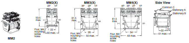
Note: Connect the common (C) of MM[]X to positive (+).
Screw Terminals
MM2(X)B, MM3(X)B,MM4(X)B
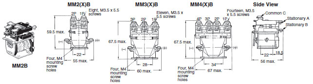
Note: Connect the common (C) of MM[]XB to positive (+).
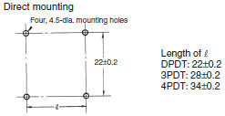
Mounting Holes (Bottom View)
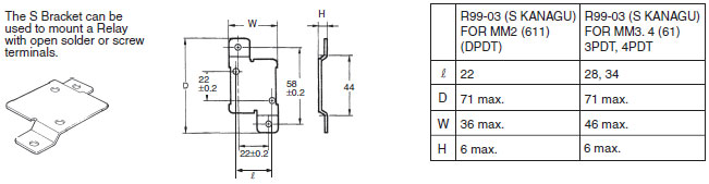
Mounting Bracket (S Bracket)
R99-03 (S KANAGU) FOR MM[]
Cased Relays
Plug-in Terminals
MM2P(N, -D)
MM2XP(N, -D)
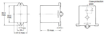
Note: As shown in the diagram, there are three 10-dia. holes in the side of the case for the MM2XP(N, -D).
When a case-protection plate is attached, the width of the Relay will be 48 mm max.
MM3P(N)
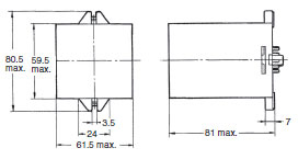
MM3PXP(N)
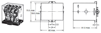
MM4P(N, -D)
MM4XP(N, -D)
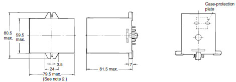
Note 1: As shown in the diagram, there are three 10-dia. holes in the side of the case for MM[]XP(N, -D).
2: When a case-protection plate is attached, the width of the Relay will be 80 mm max.
MM4P-JD
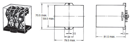
MM4XP-JD
last update: November 12, 2012
OMRON MM lineup
MM Power Relay/Lineuplast update: October 12, 2018
Available Models
When your order, specify the rated voltage.
Open Coils (with Solder Terminals)
| Type | Contact form | Relay model | Available rated voltage |
|---|---|---|---|
| Standard | DP | MM2 | 6, 12, 24, 50, 100/(110), 200/(220) VAC 6, 12, 24, 48, 100/110, 200/220 VDC |
| 3P | MM3 | 100/(110), 200/(220) VAC 6, 12, 24, 48, 200/220 VDC | |
| 4P | MM4 | 24, 100/(110), 200/(220) VAC 6, 12, 24, 48, 100/110, 200/220 VDC | |
| DC-switching | DP | MM2X | 100/(110), 200/(220) VAC 6, 12, 24, 48, 100/110, 200/220 VDC |
| 3P | MM3X | 100/(110), 200/(220) VAC 12, 24, 100/110 VDC | |
| 4P | MM4X | 100/(110), 200/(220) VAC 12, 24, 48, 100/110 VDC |
Open Coils (with Screw Terminals)
| Type | Contact form | Relay model | Available rated voltage |
|---|---|---|---|
| Standard | DP | MM2B | 6, 12, 24, 50, 100/(110), 200/(220) VAC 12, 24, 48, 100/110, 125, 200/220 VDC |
| 3P | MM3B | 6, 100/(110), 200/(220) VAC 12, 24, 100/110 VDC | |
| 4P | MM4B | 6, 100/(110), 200/(220) VAC 12, 24, 48, 100/110 VDC | |
| DC-switching | DP | MM2XB | 24, 100/(110), 200/(220) VAC 12, 24, 48, 100/110, 125, 200/220 VDC |
| 3P | MM3XB | 100/(110), 200/(220) VAC 12, 24, 48, 100/110, 125, 200/220 VDC | |
| 4P | MM4XB | 12, 24, 100/(110), 200/(220) VAC 6, 12, 24, 48, 100/110, 200/220 VDC |
Cased Coils (Plug-in Terminals)
| Type | Contact form | Relay model | Available rated voltage |
|---|---|---|---|
| Standard | DP | MM2P | 6, 12, 24, 50, 100/(110), 200/(220) VAC 6, 12, 24, 48, 100/110, 125, 200/220 VDC |
| 3P | MM3P | 6, 24, 100/(110), 200/(220) VAC 6, 12, 24, 48, 100/110, 125, 200/220 VDC | |
| 4P | MM4P | 6, 24, 50, 100/(110), 200/(220) VAC 12, 24, 48, 100/110, 125, 200/220 VDC | |
| DC-switching | DP | MM2XP | 6, 24, 100/(110), 125, 200/(220) VAC 6, 12, 24, 48, 100/110, 125, 200/220 VDC |
| 3P | MM3XP | 24, 50, 100/(110), 200/(220) VAC 12, 24, 48, 100/110, 125, 200/220 VDC | |
| 4P | MM4XP | 12, 24, 50, 100/(110), 200/(220) VAC 6, 12, 24, 48, 100/110, 125, 200/220 VDC | |
| With built-in diode | DP | MM2P-D MM4P-D | 12, 24, 48, 100/110, 200/220 VDC 12, 24, 48, 100/110, 125, 200/220 VDC |
| DC-switching with built-in diode | DP | MM2XP-D MM4XP-D | 12, 24, 48, 100/110, 125, 200/220 VDC 12, 24, 48, 100/110, 125, 200/220 VDC |
| With operation indicator | DP | MM2PN | 6, 24, 100/(110), 200/(220) VAC 6, 12, 24, 48, 100/110, 125, 200/220 VDC |
| 3P | MM3PN | 100/(110), 200/(220) VAC 6, 12, 24, 48, 100/110, 200/220 VDC | |
| 4P | MM4PN | 24, 100/(110), 200/(220) VAC 24, 48, 100/110, 125, 200/220 VDC | |
| DC-switching with operation indicator | DP | MM2XPN | 100/(110), 200/(220) VAC 12, 24, 48, 100/110, 125, 200/220 VDC |
| 3P | MM3XPN | 100/(110), 200/(220) VAC 24, 48, 100/110, 200/220 VDC | |
| 4P | MM4XPN | 100/(110), 200/(220) VAC 12, 24, 48, 100/110, 125, 200/220 VDC | |
| Conforming to auxiliary power relay specifications | 4P | MM4P-JD | 100/(110), 110, 115, 200/(220), 220 VAC 24, 100/110, 125, 200/220 VDC |
| Conforming to auxiliary power relay specifications for DC-switching | 4P | MM4XP-JD | 100/(110), 110, 115, 200/(220) VAC 24, 48, 100/110, 125, 200/220 VDC |
Accessories (Order Separately)
Mounting Brackets
| Mounting Bracket (S bracket) | R99-03MM |
|---|
Sockets
| Relay model | DIN Track/Front-connecting Socket (screw terminals) | Back-connecting Socket (solder terminals) |
|---|---|---|
| MM2(X)P(N)(-D) | 8PFA | PL08 |
| MM3P(N) | 11PFA | PL11 |
| MM3XP(N), MM4(X)P(N)(-D) | 14PFA | PL15 |
| MM4(X)P-JD | 14PFA | --- |
last update: October 12, 2018
OMRON MM catalog
MM Power Relay/Catalog- Catalog
- Manual
- CAD
English
Global Edition
| Catalog Name | Catalog Number [size] | Last Update | |
|---|---|---|---|
| | - [3222KB] | Oct 12, 201820181012 | MM Data Sheet |
- NO. MM
- TYPE:General Purpose Relays For Control Panel
 Copyright Statement
 - DATE:2021-06-13
- Associated products:
MK-S(X) Power Relays/Features MMK Latching Relay/Features