OMRON G9BRelays/ General Purpose Relays/Special-purpose
OMRON G9B Relays
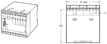
OMRON G9B Dimensions
/Images/l_967-25-118881-198x198.jpglast update: May 8, 2017
• Built-in relays switch 2 A at 250 VAC or 30 VDC.
• Initialization of stepping with reset input.
• Uses memory that stores setting status for 10 days without power. All internal contacts are released when no power is supplied.
• Detects an internal element malfunction caused by external noise, indicates the malfunction with an alarm indicator, and turns the relay alarm output ON. (An internal relay malfunction or internal relay contact weld cannot be detected.)
• With safety-design terminals which prevent electric shock accidents.
• With easy-to-see indicators which display the stepping status.
last update: May 8, 2017
Purchase the OMRON Special-purpose Please fill in the following
If you have just landed here, this product OMRON G9B Relays,Relays is offered online by Tianin FLD Technical Co.,Ltd. This is an online store providing Relays at wholesale prices for consumers. You can call us or send enquiry, we would give you the prices, packing,deliverty and more detailed information on the G9B We cooperate with DHL,TNT,FEDEX,UPS,EMS,etc.They guarantee to meet your needs in terms of time and money,even if you need your OMRON G9BRelays tomorrow morning (aka overnight or next day air) on your desk, 2, 3 days or more.Note to international customers, YES, we ship worldwide.
V430-F Series Auto Focus Multi Code Reader/Features
G3B / G3BD Solid State Relays G3[]-VD/Features
CJ1M-CPU1[]-ETN SYSMAC CJ-series CJ1M CPU Units (with Ethernet function)/Features
GT1-AD / DA Analog I/O Units/Features
eCobra 600 Lite / Standard / Pro SCARA Robots/Features
OMRON G9B catalog
G9B Stepping Relay Unit/Catalog- Catalog
- CAD
English
Global Edition
| Catalog Name | Catalog Number [size] | Last Update | |
|---|---|---|---|
| | - [641KB] | May 08, 201720170508 | G9B Data Sheet |
OMRON G9B specification
G9B Stepping Relay Unit/Specificationslast update: September 24, 2012
Contact Ratings
| Load | Resistive load (cosΦ = 1) |
|---|---|
| Rated load | 2 A at 250 VAC/30 VDC |
| Rated carry current | 2 A |
| Max. switching voltage | 250 VAC, 30 VDC |
| Max. switching current | 2 A |
Characteristics
| Operating voltage range | 85% to 110% of rated voltage |
|---|---|
| Power consumption | 24 VDC: 90 mA max. 100 or 200 VAC: 120 mA max. |
| Contact resistance (See note 2.) | 100 mΩ max. |
| Operate time (See note 3.) | 50 ms max. |
| Release time (See note 3.) | 50 ms max. |
| Min. pulse time (See note 4.) | 100 ms max. |
| Error detecting time | 100 ms max. |
| Insulation resistance (at 500 VDC) | 100 MΩ min. between the power supply, control, output, and R terminals 100 MΩ min. between the terminals, except the alarm output terminals and power output terminals |
| Dielectric strength | 1,500 V, 50/60 Hz for 1 min between the power supply, control, output, and R and other terminals 1,500 V, 50/60 Hz for 1 min between the terminals, except the alarm output terminals and power output terminals |
| Noise immunity | Noise level: 1.5 kV, pulse width: 50 ns/1 μs (600 V for 24-VDC model) |
| Vibration resistance | Destruction: 10 to 55 to 10 Hz, 0.75-mm single amplitude (1.5 mm double amplitude) Malfunction: 10 to 55 to 10 Hz, 0.75-mm single amplitude (1.5 mm double amplitude) |
| Shock resistance | Destruction: 500 m/s2 Malfunction: 200 m/s2 |
| Endurance | Mechanical: 10,000,000 steps min. Electrical: 300,000 steps min. (See note 5.) |
| Error rate (See note 6.) | 10 mA at 5 VDC |
| Ambient temperature | Operating: -25°C to 55°C (with no icing or condensation) |
| Ambient humidity | Operating: 5% to 85% |
| Terminal strength | Tightening torque: 0.98 Nm Tensile strength: 49 N |
| Weight | Twelve-step model: approx. 450 g; Six-step model: approx. 400 g |
Note: 1. The data shown above are initial values.
2. The contact resistance was measured with 0.1 A at 5 VDC using the fall-of-potential method.
3. The operate time and release time was measured with the rated voltage imposed with any contact bounce
ignored at an ambient temperature of 23°C.
4. For the step signal, set a minimum pulse time of 100 ms for both the ON time and OFF time.
5. The electrical endurance was measured at an ambient temperature of 23°C.
6. This value was measured at a switching frequency of 120 operations per minute.
last update: September 24, 2012
OMRON G9B dimension
G9B Stepping Relay Unit/Dimensionslast update: September 24, 2012
G9B-06

G9B-12

last update: September 24, 2012
OMRON G9B lineup
G9B Stepping Relay Unit/Lineuplast update: October 20, 2015
When your order, specify the rated voltage.
| No. of steps | Model | Rated voltage |
|---|---|---|
| 6 | G9B-06 | 24 VDC |
| 100 VAC | ||
| 200 VAC | ||
| 12 | G9B-12 | 24 VDC |
| 100 VAC | ||
| 200 VAC |
Note: When ordering specify the voltage.

last update: October 20, 2015
- NO. G9B
- TYPE:General Purpose Relays Special-purpose
 Copyright Statement
 - DATE:2021-06-08
- Associated products:
G4Q Ratchet Relay/Features G3PJ Solid State Relays for Heaters/Features