
OMRON H7CX-RControl Components/ Counters/General-purpose
OMRON H7CX-R Control Components
OMRON H7CX-R Dimensions
/Images/l_1450-25-118932-198x198.jpglast update: October 16, 2012
Easier to Read
Character Height: 12 mm (Large Characters)
The larger characters and wider viewing angle join a bright display for easy reading even in well-lit locations.

We increased the number of display segments to make setting parameters even easier.

Orange Added to Switchable Display Colors to Readily Show the Output Status (Status Monitoring)
Using Green When Output Is OFF Using Orange When Output Is ON

* Display colors can be switched only on models with terminal blocks.
Save Space
A Shorter Body (Make Thinner Panels)
The shorter body enables mounting in thin control panels.

Models with terminal blocks for 12 to 24 VDC. (Shortest Body)
At only 59 mm, the shortest body for any industrial counter.
Models with terminal blocks for 100 to 240 VAC. (Shortest Body)
At only 78 mm, the shortest body for any industrial counter that isolates the power supply and input circuits.
* Models with Sockets: 63.7 mm (case dimension)
The above claims apply to counters with a maximum ambient temperature of 55 ºC.
According to OMRON investigations June 2009.
Safe and Reliable
Setting Upper Limit (Prevent Unexpected Operation)
Restricting the set time help prevent incorrect settings.
Output ON Count Alarm Indication (Service Life Notification)
The number of times that the control output turns ON is counted and an alarm is displayed when a preset count is exceeded.
More Complete Lineup
Twin Counter Mode (One Unit, Two Counters)
A Twin Counter Mode has been added to enable using two counters with only one unit.
* Only two-stage models.
Replaceable Front Panel (Design Flexibility)
Replace the front panel with an Optional Front Panel to change the basic color from black to light gray or white. Optional Front Panels let you match the color of the panel or surrounding devices.

Waterproof, Dust-proof Structure
(UL508 Type 4X and IP66)
Worry-free application is possible in locations subject to water.
* When the Y92S-29 Waterproof Packing is used.

More Complete Tachometer Functionality
H7CX-R11[]
H7CX-R11W[]
A Wide Range of Input Modes
New input modes have been added to the new models.
Now you can handle a wider range of applications.
(1) One-input measurement
Measurement operation with one input.
Select the HI-LO, AREA, HI-HI, or LO-LO output mode.
(2) Independent Measurement for Two Inputs
Measurement operation with two independent inputs.

(3) Differential Input for Two Inputs
Measuring the difference between two inputs (CP1 - CP2).

(4) Absolute Ratio for Two Inputs
Measuring the ratio between two inputs (CP1/CP2).
(5) Error Ratio between Two Inputs
Measuring the ratio between two inputs ((CP1-CP2)/CP2)).

Many Other Useful Functions (NEW)
• Peak/Bottom Displays
• Output Hysteresis
• Output OFF delay
• Switching the measurement method
(pulse cycle/pulse width)
• Startup time
• Auto-zero time
• Averaging method, number of averaging times
• Prescaling
• Decimal point position
• AMD-compatible mode
last update: October 16, 2012
Purchase the OMRON General-purpose Please fill in the following
If you have just landed here, this product OMRON H7CX-R Control Components,Control Components is offered online by Tianin FLD Technical Co.,Ltd. This is an online store providing Control Components at wholesale prices for consumers. You can call us or send enquiry, we would give you the prices, packing,deliverty and more detailed information on the H7CX-R We cooperate with DHL,TNT,FEDEX,UPS,EMS,etc.They guarantee to meet your needs in terms of time and money,even if you need your OMRON H7CX-RControl Components tomorrow morning (aka overnight or next day air) on your desk, 2, 3 days or more.Note to international customers, YES, we ship worldwide.
TM Series Collaborative Robots/Features
3Z4S-LE VS-MC Series Vibrations and Shocks Resistant Lens for C-mount Cameras/Features
EE-SPX74 / SPX84 Slot-type Photomicrosensor with Connector (Modulated)/Features
CS1W-AD SYSMAC CS-series Analog I/O Unit/Features
VT-X750 High-speed automated X-ray CT inspection system/Features
OMRON H7CX-R specification
H7CX-R Tachometer/Specificationslast update: August 03, 2015
Ratings
| Classification | Tachometer | |||||
|---|---|---|---|---|---|---|
| Model | H7CX-R11[]-N | H7CX-R11W[]-N | ||||
| Input mode | 1 input only | 2 inputs only | ||||
| Ratings | Power supply voltage *1 | 100 to 240 VAC, 50/60 Hz 12 to 24 VDC or 24 VAC, 50/60 Hz | ||||
| Operating voltage fluctuation range | 85% to 110% of rated supply voltage (90% to 110% at 12 to 24 VDC) | |||||
| Power consumption | Approx. 9.4 VA at 100 to 240 VAC, Approx. 7.2 VA/4.7 W at 24 VAC/12 to 24 VDC, Approx. 3.7 W at 12 to 24 VDC | |||||
| Mounting method | Flush mounting or surface mounting | |||||
| External connections | 11-pin socket | |||||
| Degree of protection | IEC IP66, UL508 Type 4 (indoors) for panel surface only and when Y92S-29 Waterproof Packing is used | |||||
| Input signals | Count and hold | Count 1 and count 2 | ||||
| Pulse measurement method | Tachometer mode (cycle measurement) | AMD-compatible mode (continuous measurement) | Tachometer mode (cycle measurement) | |||
| Maximum counting speed | 30 Hz (minimum pulse width: 16.7 ms) | 10 kHz (minimum pulse width: 0.05 ms) | --- | 30 Hz (minimum pulse width: 16.7 ms) or 5 kHz (minimum pulse width: 0.1 ms) (selectable) | ||
| Minimum input signal width | --- | 10 ms | 1 ms | --- | ||
| Measuring ranges | 0.001 Hz to 30.00Hz | 0.001 Hz to 10 kHz | 0.026 to 999999 s | 0.003 to 999999 s | 0.01 to 5k Hz | |
| Sampling cycle | 200 ms min. | Continuous measurement (minimum interval of 10 ms) | 200 ms min. | |||
| Display refresh cycle | Input pulse of 5 Hz min. Averaging not used: 200 ms Averaging used: 200 multiplied by the averaging setting (ms) Input pulse of less than 5 Hz Averaging not used: Two times the maximum input pulse cycle Using averaging: Two times the maximum of the input pulse cycle multiplied by the averaging setting. | |||||
| Measuring accuracy | ±0.1% FS ±1 digit max. (at 23 ±5°C) | |||||
| Output mode | HI-LO, AREA, HI-HI, LO-LO | HI-HI, LO-LO | ||||
| Auto-zero time | 0.1 to 999.9 s (in Tachometer Mode) | |||||
| Startup time | 0.0 to 99.9 s | |||||
| Averaging | Simple averaging/moving averaging selectable, Number of times: OFF, 2, 4, or 8 times | |||||
| Prescaling function | 0.001 to 99.999 (in Tachometer Mode) | |||||
| Decimal point adjustment | Rightmost 3 digits | --- | ||||
| Sensor waiting time | 290 ms max. (Control output is turned OFF and no input is accepted during sensor waiting time.) | |||||
| Input | Input method | No-voltage Input Impedance when ON: 1 kΩ max. (Leakage current: 12 mA when 0 Ω), ON residual voltage: 3 V max., Impedance when OFF: 100 kΩ min. Voltage Input High (logic) level: 4.5 to 30 VDC, Low (logic) level: 0 to 2 VDC (Input resistance: approx. 4.7 kΩ) No-voltage input/voltage input (selectable) | ||||
| Hold input | Minimum input signal width: 20 ms | --- | ||||
| External power supply | 12 VDC (±10%), 100 mA * Refer to Safety Precautions (Common) on Data Sheet for details. | |||||
| Control output | Contact output: 3 A at 250 VAC/30 VDC, resistive load (cosΦ =1) Minimum applied load:10 mA at 5 VDC (failure level: P, reference value) | |||||
| Display *2 | 7-segment, negative transmissive LCD Character height Present value: 10 mm (red), comparison value: 6 mm (green) | |||||
| Digits | 6 digits (0 to 999999) | |||||
| Memory backup | EEPROM (overwrites: 100,000 times min.) that can store data for 10 years min. | |||||
| Operating temperature range | -10 to 55°C (-10 to 50°C if Counter/Tachometers are mounted side by side) (with no icing or condensation) | |||||
| Storage temperature range | -25 to 70°C (with no icing or condensation) | |||||
| Operating humidity range | 25% to 85% | |||||
| Case color | Black (N1.5) | |||||
*1. Do not use the output from an inverter as the power supply. The ripple must be 20% maximum for CC power.
*2. The display is lit only when the power is ON. Nothing is displayed when power is OFF.
Characteristics
| Insulation resistance | 100 MΩ min. (at 500 VDC) between current-carrying terminal and exposed non-current-carrying metal parts, and between non-continuous contacts | |
|---|---|---|
| Dielectric strength | 2,000 VAC, 50/60 Hz for 1 min between current-carrying metal parts and non-current-carrying metal parts 2,000 VAC (for 100 to 240 VAC), 50/60 Hz for 1 min between power supply and input circuit (1,000 VAC for 24 VAC/12 to 24 VDC) 2,000 VAC 50/60 Hz for 1 min between control output, power supply, and input circuit 1,000 VAC, 50/60 Hz for 1 min between non-continuous contacts | |
| Impulse withstand voltage | 3.0 kV (between power terminals) for 100 to 240 VAC, 1.0 kV for 24 VAC/12 to 24 VDC 4.5 kV (between current-carrying terminal and exposed non-current-carrying metal parts) for 100 to 240 VAC, 1.5 kV for 24 VAC/12 to 24 VDC | |
| Noise immunity | ±1.5 kV (between power terminals) ±600 V (between input terminals) Square-wave noise by noise simulator (pulse width: 100 ns/1 μs, 1-ns rise) | |
| Static immunity | Destruction: 15 kV, Malfunction: 8 kV | |
| Vibration resistance | Destruction | 10 to 55 Hz with 0.75-mm single amplitude, each in three directions for 2 hours |
| Malfunction | 10 to 55 Hz with 0.35-mm single amplitude, each in three directions for 10 min | |
| Shock re-sistance | Destruction | 300m/s2 each in three directions, three cycles |
| Malfunction | 100m/s2 each in three directions, three cycles | |
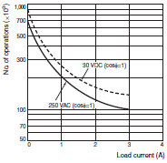
| Life expectancy | Mechanical: 10,000,000 operations min. Electrical: 100,000 operations min. (3 A at 250 VAC, resistive load, ambient temperature condition: 23°C) * | |
| Weight | Approx. 110 g (Tachometer only) | |
* See Life-test Curve (Reference Values).
Life-test Curve (Reference Values)
Resistive Load
Inductive Load
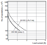
A current of 0.15 A max. can be switched at 125 VDC (cosφ=1) (Life expectancy: 100,000 operations)
A current of 0.1 A max. can be switched if L/R=7 ms.
(Life expectancy: 100,000 operations)
Applicable Standards
| Approved safety standards | cULus (or cURus): UL508/CSA C22.2 No. 14 *1 Conforms to EN 61010-1 (IEC 61010-1): Pollution degree 2/overvoltage category II, B300 PILOT DUTY, 1/4 HP 120 VAC, 1/3 HP, 240 VAC, 3-A resistive load |
|---|---|
| EMC | (EMI) EN61326-1 *2 Emission Enclosure: EN55011 Group 1 classA Emission AC mains: EN55011 Group 1 classA (EMS) EN61326-1 *2 Immunity ESD: EN61000-4-2: 4 kV contact discharge (level 2); 8 kV air discharge (level 3) Immunity RF-interference: EN61000-4-3: 10 V/m (Amplitude-modulated, 80 MHz to 1 GHz) (level 3); 10 V/m (Pulse-modulated, 900 MHz ±5 MHz) (level 3) Immunity Conducted Disturbance: EN61000-4-6: 10 V (0.15 to 80 MHz) (level 3) Immunity Burst: EN61000-4-4: 2 kV power-line (level 3); 1 kV I/O signal-line (level 4) Immunity Surge: EN61000-4-5: 1 kV line to lines (power and output lines) (level 2); 2 kV line to ground (power and output lines) (level 3) Immunity Voltage Dip/Interruption: EN61000-4-11: 0.5 cycle, 100% (rated voltage) |
*1. The following safety standards apply to the H7CX-R11[].
cUL (Listing): Applicable when an OMRON P2CF(-E) Socket is used.
cUR (Recognition): Applicable when any other socket is used.
*2. Industrial electromagnetic environment (EN/IEC 61326-1 Table 2)
I/O Functions
| Inputs | Count, count 1, count 2 | Reads counting signals. |
|---|---|---|
| Hold | Holds the measurement value and outputs. The hold indicator is lit during hold. * | |
| Outputs | OUT | Outputs signals according to the specified output mode when a comparison value is reached. |
* Refer to Data Sheet for details on the hold function.
The following table shows the delay from when the reset signal is input until the output is turned OFF. (Reference values)
| Minimum reset signal width | Output delay time |
|---|---|
| 1 ms | 0.8 to 1.2 ms |
| 20 ms | 15 to 25 ms |
last update: August 03, 2015
OMRON H7CX-R dimension
H7CX-R Tachometer/Dimensionslast update: November 12, 2012
Tachometers
Dimensions without Flush Mounting Adapter
H7CX-R[]-N

Dimensions with Flush Mounting Adapter (Adapter and Waterproof Packing Ordered Separately)
H7CX-R[]-N
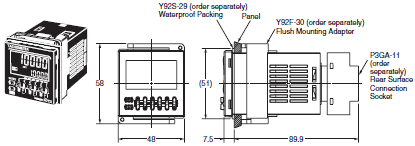
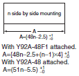
Panel Cutouts
Panel cutouts are as shown below (according to DIN43700).
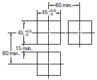
Note: 1. The mounting panel thickness should be 1 to 5 mm.
2. To allow easier operation, it is recommended that Adapters be mounted so that the gap between sides with
hooks is at least 15 mm (i.e., with the panel cutouts separated by at least 60 mm).
3. It is possible to horizontally mount Timers side by side. Attach the Flush Mounting Adapters so that the surfaces
without hooks are on the sides of the Timers. If Counters/Tachometers are mounted side by side, however,
water resistance will be lost.
Dimensions with Front Connecting Socket
H7CX-R[]-N
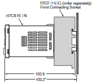
* These dimensions vary with the kind of DIN track (reference value).
last update: November 12, 2012
OMRON H7CX-R catalog
H7CX-R Tachometer/Catalog- Catalog
- Manual
- CAD
English
Global Edition
| Catalog Name | Catalog Number [size] | Last Update | |
|---|---|---|---|
| | M079-E1-01 [7790KB] | Aug 01, 201620160801 | H7CX-[]-N Data Sheet |
| | M081-E1-01 [987KB] | Jul 21, 200920090721 | H7CX-[]-N Catalog |
OMRON H7CX-R lineup
H7CX-R Tachometer/Lineuplast update: October 10, 2012
| Classifi- cation | Configuration | External connec- tions | Settings | Display digits | Outputs | Power supply voltage | Model |
|---|---|---|---|---|---|---|---|
| Tachometer | Tachometer | 11-pin socket | 1-stage (1 input and output) | 6 digits | Contact output (SPDT) | 100 to 240 VAC | H7CX-R11-N |
| 12 to 24 VDC/24 VAC | H7CX-R11D1-N | ||||||
| 1-stage (2 inputs and outputs) | Contact output (SPDT + SPST) | 100 to 240 VAC | H7CX-R11W-N | ||||
| 12 to 24 VDC/24 VAC | H7CX-R11WD1-N |
Note: The functions that are provided depend on the model. Check detailed specifications before ordering.
Accessories (Order Separately)
Front Panels (Replacement Part)
| Model | Color | Applicable Counters |
|---|---|---|
| Y92P-CXC4G | Light gray (5Y7/1) | 4-digit Counter |
| Y92P-CXC4S | White (5Y9.2/0.5) | |
| Y92P-CXC4B | Black (N1.5) | |
| Y92P-CXC6G | Light gray (5Y7/1) | 6-digit Counter |
| Y92P-CXC6S | White (5Y9.2/0.5) | |
| Y92P-CXC6B | Black (N1.5) |
Note: 1. You can change the color of the Front Panel when mounting the Counter. The Counter is shipped with a black
(N1.5) Front Panel.
2. "COUNTER" is printed on the front of Replacement Front Panels.
Soft Cover
| Models | Remarks |
|---|---|
| Y92A-48F1 | --- |
Hard Cover
| Models | Remarks |
|---|---|
| Y92A-48 | --- |
Flush Mounting Adapter
| Models | Remarks |
|---|---|
| Y92F-30 | Included with models with screw terminals. |
| Y92F-45 | Use this Adapter to install the Counter/Tachometer in a cutout previously made for a DIN 72 × 72 mm device (panel cutout: 68 × 68 mm). |
Waterproof Packing
| Model | Remarks |
|---|---|
| Y92S-29 | Included with models with screw terminals. |
Connection Sockets
| Model | Classification | Connectable Counter/ Tachometers | Remarks |
|---|---|---|---|
| P2CF-11 | Front-connecting Socket | H7CX-[]11[]-N | --- |
| P2CF-11-E | Front-connecting Socket (Finger-safe Type) | Round crimp terminals cannot be used on Finger-safe Sockets. Use forked crimp terminals. | |
| P3GA-11 | Back-connecting Sockets | A Y92A-48G Terminal Cover can be used with the Socket to create a finger-safe construction. |
Terminal Covers for P3GA-11 Back-connecting Socket
| Models | Remarks |
|---|---|
| Y92A-48G | --- |
last update: October 10, 2012
- NO. H7CX-R
- TYPE:Counters General-purpose
 Copyright Statement
 - DATE:2021-06-10
- Associated products:
H7CX-A Multifunction Preset Counter/Features H7BX Multifunction Counter (DIN 72 × 72)/Features