
OMRON CPM2CAutomation Systems/ Programmable Controllers/CPM
OMRON CPM2C Automation Systems
OMRON CPM2C Dimensions
/Images/l_1652-25-135787-198x198.jpglast update: February 04, 2014
An extensive range of models assures efficient machine control in an ultracompact package. CPU Units (DC power supply only) are available with relay or transistor output, terminal block or various connector options, and an optional real-time clock function. Select the output type, number of I/O points and other specifications to meet your needs. Expansion I/O Units with 8 to 32 I/O points make it possible to configure a control system with a maximum of 192 I/O points.
last update: February 04, 2014
Purchase the OMRON CPM Please fill in the following
If you have just landed here, this product OMRON CPM2C Automation Systems,Automation Systems is offered online by Tianin FLD Technical Co.,Ltd. This is an online store providing Automation Systems at wholesale prices for consumers. You can call us or send enquiry, we would give you the prices, packing,deliverty and more detailed information on the CPM2C We cooperate with DHL,TNT,FEDEX,UPS,EMS,etc.They guarantee to meet your needs in terms of time and money,even if you need your OMRON CPM2CAutomation Systems tomorrow morning (aka overnight or next day air) on your desk, 2, 3 days or more.Note to international customers, YES, we ship worldwide.
G70D-SOC16 / FOM16 Relay Terminal/Features
E32-T11NF[] Oil-resistant Fiber Units/Features
E3FA, E3RA, E3FB, E3RB Photoelectric Sensors/Features
V680S Series RFID System/Features
GX-JC03 / JC06 EtherCAT Junction Slave/Features
OMRON CPM2C lineup
CPM2C Compact PLC series/Lineuplast update: February 04, 2014
CPM2C CPU Units
| CPU Unit | Inputs | Outputs | Internal clock | Model | |
|---|---|---|---|---|---|
| Units with 10 I/O points Inputs: 6 Outputs: 4 | I/O terminal block | 6 inputs (24 V DC) | 4 relay outputs | --- | CPM2C-10CDR-D |
| Yes | CPM2C-10C1DR-D | ||||
| Units with 10 I/O points Inputs: 6 Outputs: 4 | 2 Fujitsu connectors | 6 inputs (24 V DC) | 4 sinking transistor outputs | --- | CPM2C-10CDTC-D |
| Yes | CPM2C-10C1DTC-D | ||||
| 4 sourcing transistor outputs | --- | CPM2C-10CDT1C-D | |||
| Yes | CPM2C-10C1DT1C-D | ||||
| 2 MIL connectors | 6 inputs (24 V DC) | 4 sinking transistor outputs | --- | CPM2C-10CDTM-D | |
| 4 sinking transistor outputs | Yes | CPM2C-10C1DTM-D | |||
| 4 sourcing t ransistor outputs | --- | CPM2C-10CDT1M-D | |||
| 4 sourcing transistor outputs | Yes | CPM2C-10C1DT1M-D | |||
| Units with 20 I/O points Inputs: 12 Outputs: 8 | 2 terminal blocks | 12 inputs (24 V DC) | 8 relays | --- | CPM2C-20CDR-D |
| Yes | CPM2C-20C1DR-D | ||||
| 2 Fujitsu connectors | 8 sinking transistor outputs | --- | CPM2C-20CDTC-D | ||
| Yes | CPM2C-20C1DTC-D | ||||
| 8 sourcing transistor outputs | --- | CPM2C-20CDT1C-D | |||
| Yes | CPM2C-20C1DT1C-D | ||||
| 2 MIL connectors | 12 inputs (24 V DC) | 8 sinking transistor outputs | --- | CPM2C-20CDTM-D | |
| 8 sinking transistor outputs | Yes | CPM2C-20C1DTM-D | |||
| 8 sourcing transistor outputs | --- | CPM2C-20CDT1M-D | |||
| 8 sourcing transistor outputs | Yes | CPM2C-20C1DT1M-D | |||
| Units with 32 I/O points Inputs: 16 Outputs: 16 | 2 Fujitsu connectors | 16 inputs (24 V DC) | 16 sinking transistor outputs | --- | CPM2C-32CDTC-D |
| 16 sourcing transistor outputs | --- | CPM2C-32CDT1C-D | |||
| 2 MIL connectors | 16 inputs (24 V DC) | 16 sinking transistor outputs | --- | CPM2C-32CDTM-D | |
| 16 sourcing transistor outputs | --- | CPM2C-32CDT1M-D | |||
| Programmable Slave with DeviceNet slave and CompoBus/S Master, 10 I/O points Inputs: 6 Outputs: 4 | 1 Fujitsu connector | 6 inputs (24 V DC) | 4 sinking transistor outputs | Yes | CPM2C-S100C-DRT |
| 4 sourcing transistor outputs | Yes | CPM2C-S110C-DRT | |||
| Units with CompoBus/S Master, 10 I/O points Inputs: 6 Outputs: 4 | 1 Fujitsu connector | 6 inputs (24 V DC) | 4 sinking transistor outputs | Yes | CPM2C-S100C |
| 4 sourcing transistor outputs | Yes | CPM2C-S110C | |||
Power Supply Unit
| Unit | Input | Output | Model |
|---|---|---|---|
| AC Power Supply Unit | 100 to 240 V AC | 24 V DC/600 mA | CPM2C-PA201 |
Expansion I/O Units
| Expansion I/O Unit | Inputs | Outputs | Model | |
|---|---|---|---|---|
| Units with inputs only Inputs: 8 | 1 Fujitsu connector | 8 inputs (24 V DC) | --- | CPM2C-8EDC |
| 1 MIL connector | 8 inputs (24 V DC) | --- | CPM2C-8EDM | |
| Units with inputs only Inputs: 16 | 1Fujitsu connector | 16 inputs (24 V DC) | --- | CPM2C-16EDC |
| 1 MIL connector | 16 inputs (24 V DC) | --- | CPM2C-16EDM | |
| Units with relay outputs only Outputs: 8 | I/O terminal block | --- | 8 relay outputs | CPM2C-8ER |
| 1 Fujitsu connector | --- | 8 sinking transistor outputs | CPM2C-8ETC | |
| --- | 8 sourcing transistor outputs | CPM2C-8ET1C | ||
| 1 MIL connector | --- | 8 sinking transistor outputs | CPM2C-8ETM | |
| --- | 8 sourcing transistor outputs | CPM2C-8ET1M | ||
| Units with transistor outputs only Outputs: 8 | 1 Fujitsu connector | --- | 16 sinking transistor outputs | CPM2C-16ETC |
| --- | 16 sourcing transistor outputs | CPM2C-16ET1C | ||
| 1 MIL connector | --- | 16 sinking transistor outputs | CPM2C-16ETM | |
| --- | 16 sourcing transistor outputs | CPM2C-16ET1M | ||
| Units with 10 I/O points Inputs: 6 Outputs: 4 | 1 I/O terminal block | 6 inputs (24 V DC) | 4 relay outputs | CPM2C-10EDR |
| Units with 20 I/O points Inputs: 12 Outputs: 8 | 1 I/O terminal block | 12 inputs (24 V DC) | 8 relay outputs | CPM2C-20EDR |
| Units with 24 I/O points Inputs: 16 Outputs: 8 | 2 Fujitsu connectors | 16 inputs (24 V DC) | 8 sinking transistor outputs | CPM2C-24EDTC |
| 8 sourcing transistor outputs | CPM2C-24EDT1 | |||
| 2 MIL connectors | 16 inputs (24 V DC) | 8 sinking transistor outputs | CPM2C-24EDTM | |
| 8 sourcing transistor outputs | CPM2C-24EDT1M | |||
| Units with 32 I/O points Inputs: 16 Outputs: 16 | 2 Fujitsu connectors | 16 inputs (24 V DC) | 16 sinking transistor outputs | CPM2C-32EDTC |
| 16 sourcing transistor outputs | CPM2C-32EDT1C | |||
| 2 MIL connectors | 16 inputs (24 V DC) | 16 sinking transistor outputs | CPM2C-32EDTM | |
| 16 sourcing transistor outputs | CPM2C-32EDT1M | |||
Analog I/O Units
| Product | Specifications | Model |
|---|---|---|
| Analog I/O Unit | 2 analog inputs and 1 analog output | CPM2C-MAD11 |
Temperature Sensor Unit
| Product | Specifications | Model |
|---|---|---|
| Temperature Sensor Unit | 2 inputs for thermocouples | CPM2C-TS001 |
| 2 inputs for temperature resistance thermometers | CPM2C-TS101 |
CompoBus/S I/O Link Units
| Product | Specifications | Model |
|---|---|---|
| CompoBus/S I/O Link Units | I/O Links: 8 inputs, 8 outputs | CPM2C-SRT21 |
I/O Connectors
(Connectors are not provided with CPU Unit. Select the appropriate ones from the following table. One CPU Unit requires two sets of Connectors.)
Fujitsu Connectors
| Connection method | From OMRON | From Fujitsu | |
|---|---|---|---|
| Soldered | C500-CE241 | 1 set | FCN-361J024-AUConnector FCN-360C024-J2Connector Cover |
| Crimped | C500-CE242 | FCN-363J024Housing FCN-363J-AUContacts FCN-360C024-J2Connector Cover | |
| Pressure-welded | C500-CE243 | FCN-367J024-AU/F | |
MIL Connectors
| Connection method | Model | Number in box | Specifications |
|---|---|---|---|
| Pressure-welded | XG4M-2030-T | 100 | Poles: 20 |
Note: Any commercially available 20-pole (IDC) connectors, according to MIL-C-83503, DIN 41651 or IEC 60603-1 specification, can be used.
Programming Consoles and Cables
| Product | Model | |
|---|---|---|
| Programming Console (2-m cable attached) | CQM1-PRO01-E | |
| Programming Console (Requires separate cable. See below.) | C200H-PRO27-E | |
| Connecting Cable for connecting CQM1-PRO01-E to a peripheral port | CS1W-CN114 | |
| Connecting Cable for C200H-PRO27-E | 2-m cable | C200H-CN222 |
| 4-m cable | C200H-CN422 | |
| Connecting Cable for C200H-PRO27-E allowing direct connection to the CPM2C CPU Unit | 2-m cable | CS1W-CN224 |
| 6-m cable | CS1W-CN624 | |
Support Software
| Product | Functions | Model |
|---|---|---|
| CX-One | Omron's integrated software for programming and configuration of all control system components, including PLCs, HMI, drives, temperature controllers and advanced sensors. | CX-ONE-AL[][]C-E*1 |
*1 [][] = Number of licenses (01, 03, 10)
| Product | Model |
|---|---|
| Expansion Memory Unit | CPM1-EMU01-V1 |
| EEPROM (256 K) | EEROM-JD |
Peripheral Port Adapters and Connecting Cables
| Description | Computer port | Length | Model | |
|---|---|---|---|---|
| Personal Computer Connecting Cables | For a D-sub 9-pin port | 2 m | CS1W-CN226 | |
| 6 m | CS1W-CN626 | |||
| 3.3 m | CQM1-CIF02 | |||
| Peripheral Port Cable | 0.05 m | CS1W-CN114 | ||
RS-232C Cables
| Product | Computer port | Specifications | Length | Model |
|---|---|---|---|---|
| RS-232C Cable | For a D-sub 9-pin port | --- | 2 m | XW2Z-200S-V |
| 5 m | XW2Z-500S-V | |||
| Can be used with a peripheral bus or Host Link. Uses connector that prevents ESD (electrostatic discharge.) | 2 m | XW2Z-200S-CV | ||
| 5 m | XW2Z-500S-CV |
Communications Port Connecting Cables
| Description | Cable length | Model |
|---|---|---|
| Converts to a Peripheral port and RS-232C port. | 0.1 m (about 4”) | CPM2C-CN111 |
| Converts to a Peripheral port only. | 0.05 m (about 2”) | CS1W-CN114 |
| Converts to an RS-232C port only. | 0.1 m (about 4”) | CS1W-CN118 |
Simple Communications Unit
| Product | Specifications | Model |
|---|---|---|
| Simple Communications Unit | RS-485/RS-232C ports for connection to components | CPM2C-CIF21 |
Adapters
| Product | Function | Model | |
|---|---|---|---|
| Peripheral/RS 232C Adapter Unit | Peripheral port level conversion | CPM2C-CIF01-V1 | |
| RS-422/RS-485/RS-232C Adapter Unit | CPM2C-CIF11 | ||
| Link Adapter | RS-232C to RS-422A conversion | For personal computer connection (Can also be connected to the CPM2A.) | 3G2A9-AL004-E |
| RS-422A Adapter | For CPM2A connection (Can also be connected to a personal computer, but requires an external 5-V power supply.) | NT-AL001 | |
Battery
| Product | Function | Model |
|---|---|---|
| Battery | Backs up memory in the CPM2C CPU Unit. | CPM2C-BAT01 |
I/O Terminal Blocks and Connecting Cables
| Product | Description | No. of inputs/ outputs | Model |
|---|---|---|---|
| I/O Terminal Blocks | Slim type with M3 slotted screw terminal block | 20 | XW2D-20G6 |
| Flat cable connector with M2.5 slot- ted screw terminal block | 20 | XW2B-20G4 | |
| Common terminals (3-tier inputs) | --- | XW2E-20G5-IN16 | |
| Common terminals (2-tier outputs) | --- | XW2C-20G6-IO16 | |
| Product | Cable length | Model | |
|---|---|---|---|
| Special Connecting Cable | With Fujitsu connector | 0.5 m | XW2Z-050A |
| 1 m | XW2Z-100A | ||
| 1.5 m | XW2Z-150A | ||
| 2 m | XW2Z-200A | ||
| 3 m | XW2Z-300A | ||
| 5 m | XW2Z-500A | ||
| With MIL connector | 2.5 m | G79-025C | |
| 5 m | G79-050C | ||
Relay I/O Terminals and Connecting Cables
Product : Relay I/O terminals
| Mounted relay | I/O points | Processing | Rated voltage | Model | Output | Fujitsu connector | MIL connector |
|---|---|---|---|---|---|---|---|
| G7TC | 16 inputs | NPN (- common) | 24 V DC | G7TC-ID16 | --- | G79-[]00C | G79-O[]00C |
| 100 (110) V AC | G7TC-IA16 | G79-[]00C | G79-O[]00C | ||||
| 200 (220) V AC | G79-[]00C | G79-O[]00C | |||||
| 16 outputs | NPN (+ common, sinking output) | 24 V DC | G7TC-OC16 | Sink | G79-[]00C | G79-O[]00C | |
| 16 outputs | PNP (- common, sourcing output) | 24 V DC | G7TC-OC16-1 | Source | G79-[]00C | G79-O[]00C | |
| 8 outputs | NPN (+ common, sinking output) | 24 V DC | G7TC-OC08 | Sink | G79-[]00C | G79-O[]00C | |
| G6D | 16 outputs | NPN (+ common, sinking output) | 24 V DC | G70D-SOC16 | Sink | G79-[]00C | G79-O[]00C |
| PNP (- common, sourcing output) | 24 V DC | G70D-SOC16-1 | Source | G79-I[]00C | |||
| G3DZ (Power MOS FET Relay) | NPN (+ common, sinking output) | 24 V DC | G70D-FOM16 | Sink | G79-[]00C | G79-O[]00C | |
| PNP (- common, sourcing output) | 24 V DC | G70D-FOM16-1 | Source | G79-I[]00C | |||
| G6D | NPN (+ common, sinking output) | 24 V DC | G70D-VSOC16 | Sink | G79-[]00C | G79-O[]00C | |
| G3DZ (Power MOS FET Relay) | NPN (+ common, sinking output) | 24 V DC | G70D-VFOM16 | Sink | G79-[]00C | G79-O[]00C | |
| (Sold separately) G2R G3R G3RN H3RN | NPN (+ common, sinking output) | 24 V DC | G70A-ZOC16-3 | Sink | G79-[]00C | G79-O[]00C | |
| PNP (- common, sourcing output) | G70A-ZOC16-4 | Source | --- | G79-I[]00C |
| Product | Cable length | Model | |
|---|---|---|---|
| Connecting Cable with connector (1:1) | With Fujitsu connector | 1 m | G79-100C |
| 1.5 m | G79-150C | ||
| 2 m | G79-200C | ||
| 3 m | G79-300C | ||
| 5 m | G79-500C | ||
| With MIL connector | 0.25 m | G79-O25C | |
| 5 m | G79-O50C | ||
| 0.25 m | G79-I25C | ||
| 0.5 m | G79-I50C | ||
DC Power Supplies
| Product | Output voltage/current | Input voltage | Model |
|---|---|---|---|
| DC Power Supply (3 W) | 24 V DC, 0.13 A | 85 V AC to 264 V AC | S82K-00324 |
| DC Power Supply (7.5 W) | 24 V DC, 0.3 A | 85 V AC to 264 V AC | S82K-00724 |
| DC Power Supply (15 W) | 24 V DC, 0.6 A | 85 V AC to 264 V AC | S82K-01524 |
| DC Power Supply (30 W) | 24 V DC, 1.3 A | 85 V AC to 264 V AC | S82K-03024 |
| DC Power Supply (50 W) | 24 V DC, 2.1 A | 85 V AC to 264 V AC | S82K-05024 |
last update: February 04, 2014
OMRON CPM2C catalog
CPM2C Compact PLC series/Catalog- Catalog
- Manual
- CAD
English
Global Edition
| Catalog Name | Catalog Number [size] | Last Update | |
|---|---|---|---|
| | P16E-EN-03A [14546KB] | Jan 13, 201520150113 | Compact PLCs Catalog |
OMRON CPM2C dimension
CPM2C Compact PLC series/Dimensionslast update: February 04, 2014
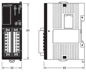
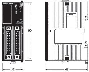
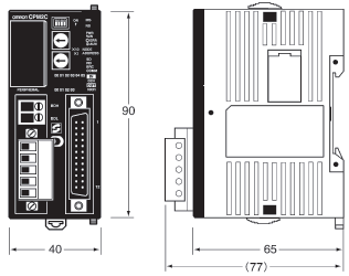
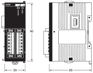
Note: All dimensions are in mm.
CPU Units with Relay Outputs
(CPM2C-10C(1)DR-D, CPM2C-20C(1)DR-D)
CPU Units with Transistor Outputs
(CPM2C-10C(1)DT(1)C-D, CPM2C-10C(1)DT(1)M-D,
CPM2C-20C(1)DT(1)C-D, CPM2C-20C(1)DT(1)M-D,
CPM2C-32CDT(1)C-D, CPM2C-32CDT(1)M-D)
CPU Units with Relay Outputs
(CPM2C-S1[]0C)

CPU Units with Transistor Outputs
(CPM2C-S1[]0C-DRT)
Units with Relay Outputs
(CPM2C-8ER, CPM2C-10EDR, CPM2C-20EDR)
Units with Transistor Outputs
(CPM2C-24EDT(1)C, CPM2C-24EDT(1)M,
CPM2C-32EDT(1)C, CPM2C-32EDT(1)M)
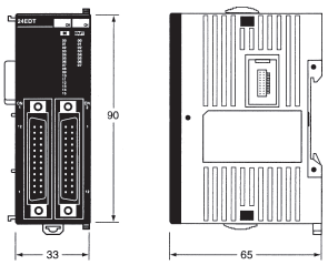
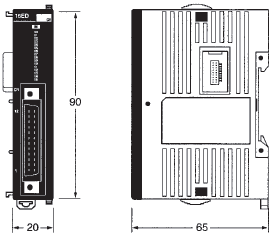
Units with Transistor Outputs Only and Units with Inputs Only
(CPM2C-8ED(1), CPM2C-8ET(1)C, CPM2C-8ET(1)M,
CPM2C-16ED(1), CPM2C-16ET(1)C, CPM2C-16ET(1)M)
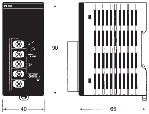
AC Power Supply Unit
(CPM2C-PA201)
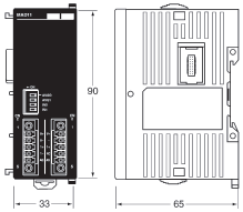
Analog I/O Unit
(CPM2C-MAD11)
Temperature Sensor Unit
(CPM2C-TS001, CPM2C-TS101)
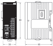
CompoBus/S I/O Link Unit
(CPM2C-SRT21)
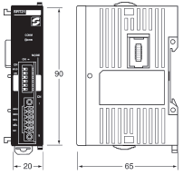
Simple Communications Unit
(CPM2C-CIF21)
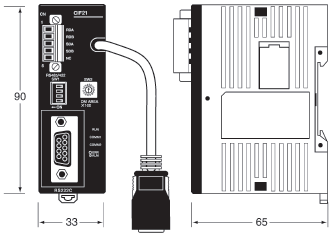
Peripheral/RS-232C Adapter Unit
(CPM2C-CIF01-V1)

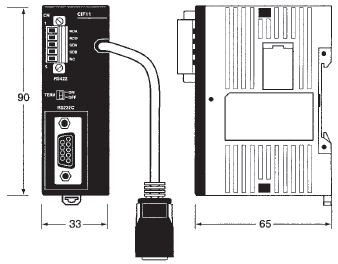
RS-422/RS-485/RS-232C Adapter Unit
(CPM2C-CIF11)
last update: February 04, 2014
OMRON CPM2C specification
CPM2C Compact PLC series/Specificationslast update: February 04, 2014
General
| Item | CPU Unit Specification | ||||||
|---|---|---|---|---|---|---|---|
| CPU Units with 10 I/O points (relay outputs) | CPU Units with 10 I/O points (transistor outputs) | CPU Units with 20 I/O points (relay outputs) | CPU Units with 20 I/O points (transistor outputs) | CPU Units with 32 I/O points (transistor outputs) | CPM2C-S CPU Unit with 10 I/O points (transistor outputs) | ||
| Supply voltage | 24 V DC | ||||||
| Operating voltage range | 20.4 to 26.4 V DC | ||||||
| Power consumption (Add Expansion Unit consumption from following tables.) | 4 W | 3 W | 4 W | 3 W | 3 W | 3 W | |
| Inrush current | 25 A max. | ||||||
| Insulation resistance | 20 MΩ min. (at 500 V DC) between isolated circuits | ||||||
| Dielectric strength | 2,300 V AC for 1 min (between isolated circuits) | ||||||
| Noise immunity | Conforms to IEC61000-4-4, 2 kV (power lines) | ||||||
| Vibration resistance | Conforming to IEC 60068-2-6, JIS C0040: 10 to 57 Hz, 0.075-mm amplitude, 57 to 150 Hz, acceleration: 9.8 m/s2 in X, Y, and Z directions for 80 minutes each (Time coefficient; 8 minutes × coefficient factor 10 = total time 80 minutes) | ||||||
| Shock resistance | Conforming to IEC 60068-2-27, JIS C0041: 147 m/s2 three times each in X, Y, and Z directions | ||||||
| Ambient temperature | Operating: 0° to 55°C Storage: -20° to 75°C (except for the battery) | ||||||
| Humidity | 10% to 90% (with no condensation) | ||||||
| Atmosphere | Must be free from corrosive gas | ||||||
| I/O interface | Terminal block | Connector | Terminal block | Connector | |||
| Power interrupt time | 2 ms min. | ||||||
| Weight | 200 g max. | 200 g max. | 250 g max. | 200 g max. | 200 g max. | 160 g max. | |
| Expansion I/O Unit with 10 I/O points (relay outputs) | 200 g max. | ||||||
| Expansion I/O Unit with 20 I/O points (relay outputs) | 200 g max. | ||||||
| Expansion I/O Units with 24 I/O points (transistor outputs) | 200 g max. | ||||||
| Expansion I/O Unit with 32 I/O points (transistor outputs) | 200 g max. | ||||||
| Expansion I/O Unit with 8 input points | 150 g max. | ||||||
| Expansion I/O Unit with 16 input points | 150 g max. | ||||||
| Expansion I/O Units with 8 output points (transistor outputs) | 150 g max. | ||||||
| Expansion I/O Units with 16 output points (transistor outputs) | 150 g max. | ||||||
| Expansion I/O Unit with 8 output points (relay outputs) | 200 g max. | ||||||
| Simple Communications Unit | 150 g max. | ||||||
| Peripheral/RS232C Adapter Unit | 150 g max. | ||||||
| RS422/RS232C Adapter Unit | 150 g max. | ||||||
| AC Power Supply Unit | 250 g max. | ||||||
| Analog I/O Unit | 200 g max. | ||||||
| Temperature Sensor Unit | 200 g max. | ||||||
| CompoBus/S I/O Link Unit | 150 g max. | ||||||
CPM2C Power Consumption
Use the following power consumption tables to calculate the total power capacity required when using a CPM2C PLC. The rated output for the CPM2C-PA201 AC Power Supply Unit is 15 W. Any surplus power not required for the PLC directly can be used as service power supply for sensors and other devices.
| CPU Unit | Power consumption (W) |
|---|---|
| CPM2C-10C(1)DR-D | 4 |
| CPM2C-20C(1)DR-D | 4 |
| CPM2C-S1[]0C-DRT1 | 3 |
| CPM2C-S1[]0C | 3 |
| CPM2C-10C(1)DT(1)[]-D | 3 |
| CPM2C-20C(1)DT(1)[]-D | 3 |
| CPM2C-32C(1)DT(1)[]-D | 3 |
The power consumption of the CPU Unit includes power for the Programming Consoles and Adapter Units.
Add the following consumptions when using Expansion I/O Units.
| Expansion I/O Unit | Power consumption (W) |
|---|---|
| CPM2C-10EDR | 1 |
| CPM2C-20EDR | 2 |
| CPM2C-24EDT(1)[] | 1 |
| CPM2C-32EDT(1)[] | 1 |
| CPM2C-MAD11 | 3.5 |
| CPM2C-SRT21 | 1 |
| CPM2C-TS001/002 | 1.5 |
| CPM2C-8ED[]/16ED[] | 1 |
| CPM2C-8ER | 2 |
| CPM2C-8ET(1)[]/16ET(1)[] | 1 |
CPM2C Characteristics
| Item | CPU Unit Specification | |||||||
|---|---|---|---|---|---|---|---|---|
| CPU Units with 10 I/O points (relay outputs) | CPU Units with 10 I/O points transistor outputs) | CPU Units with 20 I/O points (relay outputs) | CPU Units with 20 I/O points (transistor outputs) | CPU Units with 32 I/O points (transistor outputs) | CPM2C-S CPU Unit with 10 I/O points (transistor outputs) and CompoBus/S Master function | |||
| Control method | Stored program method | |||||||
| I/O control method | Cyclic scan with direct output (Immediate refreshing can be performed with IORF(97).) | |||||||
| Programming language | Ladder diagram | |||||||
| Instruction length | 1 step per instruction, 1 to 5 words per instruction | |||||||
| Instructions | Basic instructions: 14 Special instructions:105 instructions, 185 variations | |||||||
| Execution time | Basic instructions: 0.64 μs (LD instruction) Special instructions:7.8 μs (MOV instruction) | |||||||
| Program capacity | 4,096 words | |||||||
| I/O capacity | CPU Unit only | 10 points | 20 points | 32 points | 10 points | |||
| With Expansion I/O Units | 170 points max. | 180 points max. | 192 points max. | 362 points max. (106 local + 256 remote) | ||||
| Input bits | IR 00000 to IR 00915 (Words not used for input bits can be used for work bits.) | |||||||
| Output bits | IR 01000 to IR 01915 (Words not used for output bits can be used for work bits.) | |||||||
| CompoBus/S input bits | --- | 128 inputs: IR 02000 to IR 02715 | I/O bits not used for I/ O be used as work bits. | |||||
| CompoBus/S output bits | --- | 128 outputs: IR 03000 to IR 03715 | ||||||
| Work bits | 928 bits:IR 02000 to IR 04915 (Words IR 020 to IR 049) and IR 20000 to IR 22715 (Words IR 200 to IR 227) | 672 bits: IR 02800 to IR 02915 (Words IR 028 to IR 029), IR 03800 to IR 04915 (Words IR 038 to IR 049)and IR 20000 to IR 22715 (Words IR 200 to IR 227 | ||||||
| Special bits (SR area) | 448 bits: SR 22800 to SR 25515 (Words SR 228 to SR 255) | |||||||
| Temporary bits (TR area) | 8 bits (TR0 to TR7) | |||||||
| Holding bits (HR area) | 320 bits: HR 0000 to HR 1915 (Words HR 00 to HR 19) | |||||||
| Auxiliary bits (AR area) | 384 bits: AR 0000 to AR 2315 (Words AR 00 to AR 23) | |||||||
| Link bits (LR area) | 256 bits: LR 0000 to LR 1515 (Words LR 00 to LR 15) | |||||||
| Timers/Counters | 256 timers/counters (TIM/CNT 000 to TIM/CNT 255) 1-ms timers: TMHH(--) 10-ms timers: TIMH(15) 100-ms timers: TIM 1-s/10-s timers: TIML(--) Decrementing counters: CNT Reversible counters: CNTR(12) | |||||||
| Data memory | Read/Write: 2,048 words (DM 0000 to DM 2047)* Read-only: 456 words (DM 6144 to DM 6599) PC Setup: 56 words (DM 6600 to DM 6655) *The Error Log is contained in DM 2000 to DM 2021. | |||||||
| CompoBus/S master functions | --- | --- | Connects to up to 32 slaves with up to 256 I/O link points | |||||
| DeviceNet slave functions | --- | --- | DeviceNet remote I/O link (DRT model only) Up to 1,024 I/O link points Explicit messages Read/write of specified areas from PLC with Master Unit | |||||
| Basic interrupts | Interrupt processing | 2 interrupts | 2 interrupts | 4 interrupts | 4 interrupts | 4 interrupts | 2 interrupts | |
| Shared by the external interrupt inputs (counter mode) and the quick-response inputs. | ||||||||
| Interval timer interrupts | 1 (Scheduled Interrupt Mode or Single Interrupt Mode) | |||||||
| Highspeed counter | High-speed counter | One high-speed counter: 20 kHz single-phase or 5 kHz two-phase (linear count method) Counter interrupt: 1 (set value comparison or set-value range comparison) | ||||||
| Highspeed counter | Interrupt inputs (Counter mode) | 2 inputs | 2 inputs | 4 inputs | 4 inputs | 4 inputs | 2 inputs | |
| Shared by the external interrupt inputs and the quick-response inputs. | ||||||||
| Counter interrupts | 2 inputs | 2 inputs | 4 inputs | 4 inputs | 4 inputs | 2 inputs | ||
| Shared by the external interrupt inputs and the quick-response inputs. | ||||||||
| Pulse output | Two points with no acceleration/deceleration, 10 Hz to 10 kHz each, and no direction control. One point with trapezoid acceleration/deceleration, 10 Hz to 10 kHz, and direction control. Two points with variable duty-ratio outputs (using PWM(--)). (Pulse outputs can be used with transistor outputs only, they cannot be used with relay outputs.) | |||||||
| Synchronized pulse control | One point: A pulse output can be created by combining the high-speed counter with pulse outputs and multiplying the frequency of the input pulses from the high-speed counter by a fixed factor. (This output is possible with transistor outputs only, it cannot be used with relay outputs.) | |||||||
| Quick-response inputs | 2 inputs | 2 inputs | 4 inputs | 4 inputs | 4 inputs | 2 inputs | ||
| Shared by the external interrupt inputs and the interrupt inputs (counter mode). Min. input pulse width: 50 μs max. | ||||||||
| Input time constant (ON response time = OFF response time) | Can be set for all input points. (1 ms, 2 ms, 3 ms, 5 ms, 10 ms, 20 ms, 40 ms, or 80 ms) | |||||||
| Clock function | Shows the year, month, day of the week, day, hour, minute, and second. (Battery backup) | |||||||
| Communications functions | Peripheral port: Supports Host Link, peripheral bus, no-protocol, or Programming Console connections. RS-232C port: Supports Host Link, no-protocol, 1:1 Slave Unit Link, 1:1 Master Unit Link, or 1:1 NT Link connections. A CPM2C-CN111, CS1W-CN114, or CS1W-CN118 Connecting Cable, or an Interface Unit (CPM2C-CIF01-V1 or CPM2C-CIF11) is required to connect to the CPM2C’s communications port. | |||||||
| Memory protection | HR area, AR area, program contents, read/write DM area contents, and counter values are maintained during power interruptions. | |||||||
| Memory backup | Flash memory: Program, read-only DM area, and PC Setup Memory backup: The read/write DM area, HR area, AR area, and counter values are backed up. With CPU Units that are equipped with a clock, the battery will backup memory for 2 years at 25°C. With CPU Units that are not equipped with a clock, if a battery is not installed, the internal capacitor will backup memory for 10 days at 25°C. If a battery (optional CPM2C-BAT01 Battery) is installed, it will backup memory for 5 years at 25°C. | |||||||
| Self-diagnostic functions | CPU Unit failure (watchdog timer), I/O bus error, battery error, and memory failure | |||||||
| Program checks | No END instruction, programming errors (checked when operation is started) | |||||||
CPM2C I/O Specifications
CPU Unit Input Specifications
| Item | Specifications | Circuit configuration | ||
|---|---|---|---|---|
| Units with 10 I/O points | Units with 20 I/O points | Units with 32 I/O points | ||
| Input voltage | 24 V DC +10%/-15% | 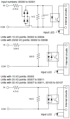 | ||
| Input impedance | impedance IN00000 to IN00001: 2.7 kΩ IN00002 to IN00004: 3.9 kΩ IN00005: 4.7 kΩ | IN00000 to IN00001: 2.7 kΩ IN00002 to IN00006: 3.9 kΩ IN00007 and up: 4.7 kΩ | IN00000 to IN00001: 2.7 kΩ IN00002 to IN00006: 3.9 kΩ IN00007: 4.7 kΩ IN00100 to IN00107: 4.7 kΩ | |
| Input current | IN00000 to IN00001: 8 mA IN00002 to IN00004: 6 mA IN00005: 5 mA | IN00000 to IN00001: 8 mA IN00002 to IN00006: 6 mA IN00007 and up: 5 mA | IN00000 to IN00001: 8 mA IN00002 to IN00006: 6 mA IN00007: 5 mA IN00100 to IN00107: 5 mA | |
| ON voltage/ current | IN00000 to IN00001:17 V DC min., 5 mA IN00002 and up:14.4 V DC min., 3.5 mA | |||
| OFF voltage/ current | 5.0 V DC max., 1.1 mA | |||
| ON delay | 1 to 80 ms max. Default: 10 ms (See note.) | |||
| OFF delay | 1 to 80 ms max. Default: 10 ms (See note.) | |||
Note: The input time constant can be set to 1, 2, 3, 5, 10, 20, 40, or 80 ms in the PC Setup.
High-speed Counter Inputs
The following CPU Unit input bits can be used as high-speed counter inputs. The maximum count frequency is 5 kHz in differential phase mode and 20 kHz in the other modes.
| Input | Function | |||
|---|---|---|---|---|
| Differential phase mode | Pulse plus direction input mode | Up/down input mode | Increment mode | |
| IN00000 | A-phase pulse input | Pulse input | Increment pulse input | Increment pulse input |
| IN00001 | B-phase pulse input | Direction input | Decrement pulse input | Normal input |
| IN00002 | Z-phase pulse input or hardware reset input (IN00002 can be used as a normal input when it is not used as a high-speed counter input.) | |||
Interrupt Inputs
CPM2C PCs have inputs that can be used as interrupt inputs (interrupt input mode or counter mode) and quick-response inputs. The minimum pulse width for these inputs is 50 μs.
In CPU Units with 10 I/O points, inputs IN00003 and IN00004 can be used as interrupt inputs. In CPU Units with 20 or 32 I/O points, inputs IN00003 through IN00006 can be used as interrupt inputs.
Expansion I/O Unit Input Specifications
| Item | Specification |
|---|---|
| Input voltage | 24 V DC +10%/-15% |
| Input impedance | 4.7 kΩ |
| Input current | 5 mA |
| ON voltage/current | 14.4 V DC min., 3.5 mA |
| OFF voltage/current | 5.0 V DC max., 1.1 mA |
| ON delay | 1 to 80 ms max. Default: 10 ms (See note.) |
| OFF delay | 1 to 80 ms max. Default: 10 ms (See note.) |
| Circuit configuration | 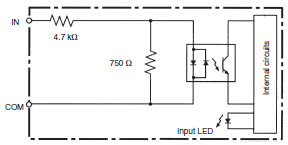 |
Note: The input time constant can be set to 1, 2, 3, 5, 10, 20, 40, or 80 ms in the PC Setup.
CPM2C Output Specifications (CPU Units and Expansion I/O Units)
Relay Output
| Item | Specification |
|---|---|
| Max. switching capacity | 2 A, 250 V AC (cosφ = 1) 2 A, 24 V DC (4 A/common) |
| Min. switching capacity | 10 mA, 5 V DC |
| Service life of relay | Electrical:150,000 operations (24- V DC resistive load) 100,000 operations (240- V AC inductive load, cosφ = 0.4) Mechanical:20,000,000 operations |
| ON delay | 15 ms max. |
| OFF delay | 15 ms max. |
| Circuit configuration | 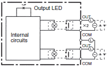 |
Transistor Outputs (Sinking or Sourcing) for CPU Units and Expansion I/O Units
| Item | Specification |
|---|---|
| Max. switching capacity | CPU Units with 10 or 20 I/O Points 01000 to 01007: 40 mA at 4.5 V DC to 300 mA at 20.4 V DC, 300 mA (20.4 to 26.4 V) CPU Units with 32 I/O Points 01000 to 01007: 40 mA at 4.5 V DC to 300 mA at 20.4 V DC, 300 mA (20.4 to 26.4 V) 01100 to 01107: 40 mA at 4.5 V DC to 100 mA at 20.4 V DC, 100 mA (20.4 to 26.4 V) (See note.) Expansion I/O Units 01[]00 to 01[]07: 40 mA at 4.5 V DC to 300 mA at 20.4 V DC, 300 mA (20.4 to 26.4 V) 01[]08 to 01[]15: 40 mA at 4.5 V DC to 100 mA at 20.4 V DC, 100 mA (20.4 to 26.4 V) (See note.) |
| Min. switching capacity | 0.5 mA |
| Max. inrush current | 0.9 A for 10 ms (charging and discharging waveform) |
| Leakage current | 0.1 mA max. |
| Residual voltage | 0.8 V max. |
| ON delay | OUT01000 and OUT01001:20 μs max. OUT01002 and up:0.1 ms max. |
| OFF delay | OUT01000 and OUT01001:40 μs max. for 4.5 to 26.5 V, 10 to 300 mA 0.1 ms max. for 4.5 to 30 V, 0.5 to 10 mA OUT01002 and up:1 ms max. |
| Fuse | 1 fuse for each 2 outputs (The fuse cannot be replaced by the user.) |
| Circuit configuration | 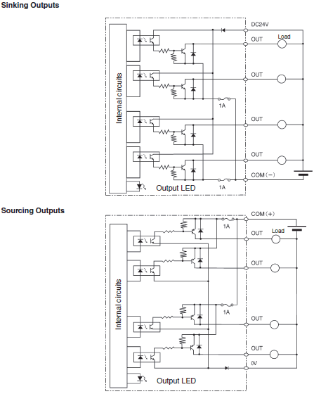 |
Note: Connect dummy resistance as required and maintain the load current between 10 and 150 mA when using
01000 and 01001 for pulse outputs. The ON/OFF response time will increase if the load current is below 10 mA,
preventing outputting high-speed pulses. The transistors will heat if the output current is greater than 150 mA,
possibly destroying the elements.
last update: February 04, 2014
- NO. CPM2C
- TYPE:Programmable Controllers CPM
 Copyright Statement
 - DATE:2021-06-09
- Associated products:
CP1W-MODTCP61 CP1 Modbus/TCP Adapter/Features CP1W-EIP61 EtherNet/IP Communication Module for CP1L/CP1H PLCs/Features