OMRON MK-SRelays/ General Purpose Relays/For Control Panel
OMRON MK-S Relays
OMRON MK-S Dimensions
/Images/l_1938-25-118981-198x198.jpglast update: April 24, 2017
• Same mounting and internal wiring as the previous Super MK Relays
• Built-in mechanical indicator enables checking contact operation.
• Two modes can be used to check circuits for models with latching lever.
• Nameplate provided on models with latching lever.
• All materials are RoHS compliant.
• UL and IEC (TÜV) certification.

Example of Applications of Models with Latching Levers
Operation checks in relay sequence circuits
last update: April 24, 2017
Purchase the OMRON For Control Panel Please fill in the following
If you have just landed here, this product OMRON MK-S Relays,Relays is offered online by Tianin FLD Technical Co.,Ltd. This is an online store providing Relays at wholesale prices for consumers. You can call us or send enquiry, we would give you the prices, packing,deliverty and more detailed information on the MK-S We cooperate with DHL,TNT,FEDEX,UPS,EMS,etc.They guarantee to meet your needs in terms of time and money,even if you need your OMRON MK-SRelays tomorrow morning (aka overnight or next day air) on your desk, 2, 3 days or more.Note to international customers, YES, we ship worldwide.
3G3MX2-V1 Multi-function Compact Inverter/Features
NT11 / NT21 Programmable Terminals/Features
Y92[] Accessories/Features
A22R/M22R Pushbutton Switches / Indicators/Features
E52 (Exclusive Models) Temperature Sensor (Exclusive Models)/Features
OMRON MK-S lineup
MK-S General-purpose Relays/Lineuplast update: October 13, 2015
When your order, specify the rated voltage.
| Type | Terminals | Contact form | Internal connections (See note 3.) | With mechanical indicator | With mechanical indicator and lockable test button | Coil ratings |
|---|---|---|---|---|---|---|
| Standard Models | Plug-in | DPDT | Standard | MKS2P | MKS2PI | AC/DC |
| Non-standard | MKS2P-2 | MKS2PI-2 | ||||
| 3PDT | Standard | MKS3P | MKS3PI | |||
| Non-Standard | MKS3P-2 | MKS3PI-2 | ||||
| MKS3P-5 | MKS3PI-5 | |||||
| Models with LED Indicator (See note 2.) | DPDT | Standard | MKS2PN(1) | MKS2PIN(1) | AC/DC | |
| Non-standard | MKS2PN(1)-2 | MKS2PIN(1)-2 | ||||
| 3PDT | Standard | MKS3PN(1) | MKS3PIN(1) | |||
| Non-Standard | MKS3PN(1)-2 | MKS3PIN(1)-2 | ||||
| MKS3PN(1)-5 | MKS3PIN(1)-5 | |||||
| Models with Diode (See note 2.) | DPDT | Standard | MKS2P(1)-D | MKS2PI(1)-D | DC | |
| Non-standard | MKS2P(1)-D-2 | MKS2PI(1)-D-2 | ||||
| 3PDT | Standard | MKS3P(1)-D | MKS3PI(1)-D | |||
| Non-Standard | MKS3P(1)-D-2 | MKS3PI(1)-D-2 | ||||
| MKS3P(1)-D-5 | MKS3PI(1)-D-5 | |||||
| Models with LED Indicator and Diode | DPDT | Standard | MKS2PN-D | MKS2PIN-D | DC | |
| Non-standard | MKS2PN-D-2 | MKS2PIN-D-2 | ||||
| 3PDT | Standard | MKS3PN-D | MKS3PIN-D | |||
| Non-Standard | MKS3PN-D-2 | MKS3PIN-D-2 | ||||
| MKS3PN-D-5 | MKS3PIN-D-5 | |||||
| Models with Varistor | DPDT | Standard | MKS2P-V | MKS2PI-V | AC | |
| Non-standard | MKS2P-V-2 | MKS2PI-V-2 | ||||
| 3PDT | Standard | MKS3P-V | MKS3PI-V | |||
| Non-Standard | MKS3P-V-2 | MKS3PI-V-2 | ||||
| MKS3P-V-5 | MKS3PI-V-5 | |||||
| Models with LED Indicator and Varistor | DPDT | Standard | MKS2PN-V | MKS2PIN-V | AC | |
| Non-standard | MKS2PN-V-2 | MKS2PIN-V-2 | ||||
| 3PDT | Standard | MKS3PN-V | MKS3PIN-V | |||
| Non-Standard | MKS3PN-V-2 | MKS3PIN-V-2 | ||||
| MKS3PN-V-5 | MKS3PIN-V-5 |
Note: 1. When ordering, add the rated voltage to the model number. Rated voltages are given in the coil ratings table in
the specifications.

Note: 2. The DC coil comes in two types: standard coil polarity and reverse coil polarity.
Refer to Terminal Arrangement and Internal Connections (Bottom View).

Note: 3. Refer to Terminal Arrangement and Internal Connections (Bottom View) for non-standard internal connections.
List of Models (Order Separately)
| Item | Type | Model |
|---|---|---|
| Track-mounted Socket | 8-pin | PF083A-E |
| 11-pin | PF113A-E | |
| 8-pin | PF083A-D | |
| 11-pin | PF113A-D | |
| Hold-down Clip (For PF083A-E and PF113A-E) | PFC-A1 | |
last update: October 13, 2015
OMRON MK-S catalog
MK-S General-purpose Relays/Catalog- Catalog
- Manual
- CAD
English
Global Edition
| Catalog Name | Catalog Number [size] | Last Update | |
|---|---|---|---|
| | - [2264KB] | Oct 13, 201520151013 | MK-S Data Sheet |
OMRON MK-S specification
MK-S General-purpose Relays/Specificationslast update: September 24, 2012
Ratings
Coil Ratings
| Rated voltage | Rated current | Coil resistance | Must operate voltage | Must release voltage | Max. voltage | Power consumption | ||
|---|---|---|---|---|---|---|---|---|
| 50 Hz | 60 Hz | |||||||
| AC | 6 V | 443 mA | 385 mA | 3.1 Ω | 80% max. of rated voltage | 30% min. of rated voltage at 60 Hz 25% min. of rated voltage at 50 Hz | 110% of rated voltage | Approx. 2.3 VA at 60 Hz Approx. 2.7 VA at 50 Hz |
| 12 V | 221 mA | 193 mA | 13.7 Ω | |||||
| 24 V | 110 mA | 96.3 mA | 48.4 Ω | |||||
| 100 V | 26.6 mA | 23.1 mA | 760 Ω | |||||
| 110 V | 24.2 mA | 21.0 mA | 932 Ω | |||||
| 200 V | 13.3 mA | 11.6 mA | 3,160 Ω | |||||
| 220 V | 12.1 mA | 10.5 mA | 3,550 Ω | |||||
| 230 V | 10.0 mA | 11.5 mA | 4,250 Ω | |||||
| 240 V | 11.0 mA | 9.6 mA | 4,480 Ω | |||||
| DC | 6 V | 224 mA | 26.7 Ω | 15% min. of rated voltage | Approx. 1.4 W | |||
| 12 V | 112 mA | 107 Ω | ||||||
| 24 V | 55.8 mA | 430 Ω | ||||||
| 48 V | 28.1 mA | 1,710 Ω | ||||||
| 100 V | 13.5 mA | 7,390 Ω | ||||||
| 110 V | 12.3 mA | 8,960 Ω | ||||||
| 125 V | 10.8 mA | 11,576 Ω | ||||||
Note: 1. The rated current and coil resistance are measured at a coil temperature of 23°C with tolerances of +15%/−20%
for AC rated current and ±15% for DC coil resistance.
2. Performance characteristic data are measured at a coil temperature of 23°C.
3. The maximum voltage is one that is applicable instantaneously to the Relay coil at 23°C and not continuously.
4. For DC-operated Relays with the LED indicator built-in, add an LED current of approx. 5 mA to the rated current.
Contact Ratings
| Load | Resistive load (cosΦ = 1) | Inductive load (cosΦ = 0.4) | |
|---|---|---|---|
| Contact mechanism | Single | ||
| Contact material | AgSnIn | ||
| Rated load | NO | 10 A, 250 VAC 10A, 30 VDC | 7 A, 250 VAC |
| NC | 5 A, 250 VAC 5 A, 30 VDC | ||
| Rated carry current | 10 A | ||
| Max. switching voltage | 250 VAC, 250 VDC | ||
| Max. switching current | 10 A | ||
| Max. switching power | NO | 2,500 VA/300 W | |
| NC | 1,250 VA/150 W | ||
Characteristics
| Contact resistance | 100 mΩ max. |
|---|---|
| Operate time | AC: 20 ms max. DC: 30 ms max. |
| Release time | 20 ms max. (40 ms max. for built-in Diode Relays) |
| Max. operating frequency | Mechanical: 18,000 operations/h Electrical: 1,800 operations/h (under rated load) |
| Insulation resistance | 100 MΩ min. (at 500 VDC) |
| Dielectric strength | 2,500 VAC 50/60 Hz for 1 min between coil and contacts 1,000 VAC 50/60 Hz for 1 min between contacts of same polarity and terminals of the same polarity 2,500 VAC 50/60 Hz for 1 min between current-carrying parts, non-current-carrying parts, and opposite polarity |
| Insulation method | Basic insulation |
| Impulse withstand voltage | 4.5 kV between coil and contacts (with 1.2 × 50 μs impulse wave) 3.0 kV between contacts of different polarity (with 1.2 × 50 μs impulse wave) |
| Pollution degree | 3 |
| Rated insulation voltage | 250 V |
| Vibration resistance | Destruction: 10 to 55 to 10 Hz, 0.75-mm single amplitude (1.5-mm double amplitude) Malfunction: 10 to 55 to 10 Hz, 0.5-mm single amplitude (1.0-mm double amplitude) |
| Shock resistance | Destruction: 1,000 m/s2 (approx. 100 G) Malfunction: 100 m/s2 (approx. 10 G) |
| Endurance | Mechanical: 5,000,000 operations min. (at 18,000 operations/h under rated load) Electrical: 100,000 operations h. (at 1,800 operations/h under rated load) |
| Failure rate P level (reference value) | 10 mA at 1 VDC |
| Ambient temperature | Operating: -40 to 60°C (with no icing or condensation) |
| Ambient humidity | Operating: 5% to 85% |
| Weight | Approx. 90 g |
Note: 1. The values given above are initial values.
2. P level: λ60 = 0.1 × 10⁻⁶/operation
3. Ambient temperature of models with LED indicator is −25 to 60°C.
last update: September 24, 2012
OMRON MK-S dimension
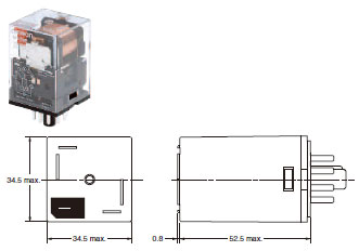
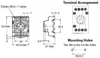
MK-S General-purpose Relays/Dimensionslast update: November 12, 2012
Models without Latching Lever
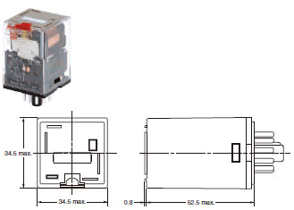
Models with Latching Lever
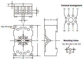
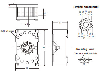
Sockets
See below for Socket dimensions.
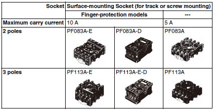
Note: Use the Surface-mounting Sockets (i.e., finger-protection models) with "-E" at the end of the model number. When
using the PF083A and PF113A, be sure not to exceed the Socket's maximum carry current of 5 A. Using at a current
exceeding 5 A may lead to burning. Round terminals cannot be used for finger-protection models. Use Y-shaped
terminals.
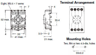
PF083A-E (Conforming to EN 50022)
PF113A-E (Conforming to EN 50022)
PF083A-D
PF113A-D
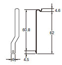
Hold-down Clips
PFC-A1
(2 pieces per set)
Mounting Tracks
PFP-100N, PFP-50N
(Conforming to EN 50022)

PFP-100N2
(Conforming to EN 50022)

Mounting Height with Sockets
Surface-mounting Sockets
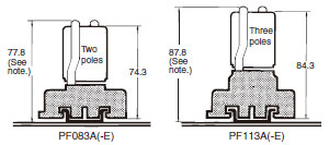
Note: PF083A(-E) and PF113A(-E) allow either track or screw mounting.
last update: November 12, 2012
- NO. MK-S
- TYPE:General Purpose Relays For Control Panel
 Copyright Statement
 - DATE:2021-06-07
- Associated products:
G7T I/O Relay/Features MK-S(X) Power Relays/Features