OMRON H8PSControl Components/ Cam Positioners/ Copyright Statement
OMRON H8PS Control Components
OMRON H8PS Dimensions
/Images/l_236-25-118939-198x198.jpglast update: December 19, 2013
• Compact 8-, 16-, and 32-output Models available that are 1/4- DIN size at 96 x 96 mm.
• High-speed operation at 1,600 r/min and high-precision settings to 0.5° ensure widespread application.
• Highly visible display with backlit negative transmissive LCD.
• Advance angle compensation function to compensate for output delays.
• Bank function for multi-product production (8 banks).
(H8PS-16[]/-32[] models.)
• Speed display and pulse output.
• Approved standards: UL/CSA and EMC.
last update: December 19, 2013
Purchase the OMRON Copyright Statement Please fill in the following
If you have just landed here, this product OMRON H8PS Control Components,Control Components is offered online by Tianin FLD Technical Co.,Ltd. This is an online store providing Control Components at wholesale prices for consumers. You can call us or send enquiry, we would give you the prices, packing,deliverty and more detailed information on the H8PS We cooperate with DHL,TNT,FEDEX,UPS,EMS,etc.They guarantee to meet your needs in terms of time and money,even if you need your OMRON H8PSControl Components tomorrow morning (aka overnight or next day air) on your desk, 2, 3 days or more.Note to international customers, YES, we ship worldwide.
NS Series Programmable Terminals/Features
D4A-[]N General-purpose Limit Switch/Features
A22[] Knob-type Selector Switch (Cylindrical 22/25-dia.)/Features
CS1W-B7A CS-series B7A Interface Unit/Features
XS5[]R Oil-resistant Connectors/Features
OMRON H8PS specification
H8PS Cam Positioner/Specificationslast update: September 24, 2012
Ratings
| Item | H8PS-[]B | H8PS-[]BF | H8PS-[]BP | H8PS-[]BFP | ||
|---|---|---|---|---|---|---|
| Rated supply voltage | 24 VDC | |||||
| Operating voltage range | 85% to 110% of rated supply voltage | |||||
| Mounting method | Flush mounting | Surface mounting, track mounting | Flush mounting | Surface mounting, track mounting | ||
| Power consumption | Approx. 4.5 W at 26.4 VDC for 8-output models Approx. 6.0 W at 26.4 VDC for 16-/32-output models | |||||
| Inputs | Encoder input | Connections to a dedicated absolute encoder | ||||
| External inputs | Input signals | 8-output Models: None 16-/32-output Models: Bank inputs 1/2/4, origin input, start input | ||||
| Input type | No voltage inputs: ON impedance:1 kΩ max. (Leakage current: approx. 2 mA at 0 Ω) ON residual voltage: 2 V max., OFF impedance: 100 kΩ min., Applied voltage: 30 VDC max. Minimum input signal width: 20 ms | |||||
| Outputs | Cam outputs RUN output | NPN open-collector transistor outputs 30 VDC max., 100 mA max. (Do not exceed 1.6 A total for all cam outputs and the RUN output.), residual voltage: 2 VDC max. | PNP open-collector transistor outputs 30 VDC max. (26.4 VDC for 16-/32-output Models), 100 mA max. (Do not exceed 1.6 A total for all cam outputs and the RUN output.), residual voltage: 2 VDC max. | |||
| Pulse output | NPN open-collector transistor output 30 VDC max., 30 mA max., residual voltage: 0.5 VDC max. | PNP open-collector transistor output 30 VDC max. (26.4 VDC for 16-/32-output Models) 30 mA max., residual voltage: 2 VDC max. | ||||
| Number of outputs | 8-output Models: 8 cam outputs, 1 RUN output, 1 pulse output 16-output Models: 16 cam outputs, 1 RUN output, 1 pulse output 32-output Models: 32 cam outputs, 1 RUN output, 1 pulse output | |||||
| Number of banks | 8 banks (for 16-/32-output Models only) | |||||
| Display method | 7-segment, negative transmissive LCD (Main Display: 11 mm (red), Sub-display: 5.5 mm (green)) | |||||
| Memory backup method | EEPROM (overwrites: 100000 times min.) that can store data for 10 years min. | |||||
| Ambient operating temperature | -10 to 55°C (with no icing or condensation) | |||||
| Storage temperature | -25 to 65°C (with no icing or condensation) | |||||
| Ambient humidity | 25% to 85% | |||||
| Degree of protection | Panel surface: IP40, Rear case: IP20 | |||||
| Case color | Light gray (Munsell 5Y7/1) | |||||
Characteristics
| Setting unit | 0.5° increments at a resolution of 720, 1° increments at a resolution of 256 or 360 *1 | |
|---|---|---|
| Number of steps | Up to 10 steps can be set for each cam to turn the output ON/OFF 10 times. *2 | |
| Inputs | Encoder input | Connections to a dedicated absolute encoder Response rotation speed (in Run/Test Mode) 1600 r/min max. at a resolution of 256 or 360 (1200 r/min max. if ADV function is set for 4 or more cams) *3 *4 800 r/min max. at a resolution of 720 (600 r/min max. if ADV function is set for 4 or more cams) Includes error data detection |
| Encoder cable extension distance | 256/360 resolution 100 m max. at 330 r/min or less 52 m max. at 331 to 1200 r/min (331 to 900 r/min if ADV function is set for 4 or more cams) 12 m max. at 1201 to 1600 r/min (901 to 1200 r/min if ADV function is set for 4 or more cams) 720 resolution 100 m max. at 330 r/min or less 52 m max. at 331 to 600 r/min (331 to 450 r/min if ADV function is set for 4 or more cams) 12 m max. at 601 to 800 r/min (451 to 600 r/min if ADV function is set for 4 or more cams) | |
| Output response time | 0.3 ms max. | |
| Insulation resistance | 100 MΩ min. (at 500 VDC) between current-carrying terminals and exposed non-current-carrying metal parts, between all current-carrying parts and the USB connector | |
| Dielectric strength | 1000 VAC, 50/60 Hz for 1 min between current-carrying terminals and exposed non-current-carrying metal parts 500 VAC, 50/60 Hz for 1 min between current-carrying section and USB connector, and between current- carrying terminals and non-current-carrying metal part of output connector | |
| Impulse withstand voltage | 1 kV between power terminals 1.5 kV between current-carrying terminals and exposed non-current-carrying metal parts | |
| Noise immunity | ±480 V between power terminals, ±600 V between input terminals Square-wave noise by noise simulator (pulse width: 100 ns/1 μs, 1-ns rise) | |
| Static immunity | 8 kV (malfunction), 15 kV (destruction) | |
| Vibration resistance | Destruction | 10 to 55 Hz with 0.75-mm single amplitude each in 3 directions for 2 hours each |
| Malfunction | 10 to 55 Hz with 0.5-mm single amplitude each in 3 directions for 10 minutes each | |
| Shock resistance | Destruction | 300 m/s2 3 times each in 6 directions |
| Malfunction | 200 m/s2 3 times each in 6 directions | |
| Approved safety standards | cULus (Listing): UL508/CSA C22.2 No. 14 | |
| EMC | (EMI) EN61326 Emission Enclosure: EN55011 Group1 Class A (EMS) EN61326 Immunity ESD: EN61000-4-2: 4 kV contact discharge, 8 kV air discharge Immunity RF-interference: EN61000-4-3: 10 V/m (Amplitude-modulated, 80 MHz to 1 GHz), 10 V/m (Pulse- modulated, 900 MHz ±5 MHz) Immunity Conducted Disturbance EN61000-4-6: 10 V (0.15 to 80 MHz) Immunity Burst: EN61000-4-4: 2 kV for power-line, 1 kV for I/O signal-line Immunity Surge: EN61000-4-5: 1 kV line to line (power line), 2 kV line to ground (power line) | |
| Weight | Approx. 300 g (Cam Positioner main unit only) | |
Note:Cam output precision, however, is 2° max. for Encoder with 256 resolution (P/R).
Note:Although 32-output Models can have 10 steps set for any one output, there must be no more than 160 steps total set for all cam outputs.
Note:The maximum is 1000 r/min when an E6CP-AG5C-C Encoder is connected.
Note:ADV stands for Advance Angle Compensation.
Functions
| Item | H8PS-8[] | H8PS-16[] | H8PS-32[] |
|---|---|---|---|
| Encoder rotation direction switching | Encoder data can be set with a DIP switch to forward (CW) or reverse (CCW) direction. | ||
| Encoder origin designation | The present display angular position can be set to 0° (origin) by pressing the ORIGIN Key on the front panel. | The present display angular position can be set to 0° (origin) by using the origin input terminal or the ORIGIN Key on the front panel. Note:All banks use the same origin. | |
| Angle display switch | Converts the Absolute Encoder value display from 256 divisions/revolution to 360°/revolution. | ||
| Rotation display monitor | Graphically displays the Encoder rotational angular position. | ||
| Teaching function | Sets the cam output ON/OFF angle based on actual machine (Encoder) operation. | ||
| Pulse output | Outputs a preset number of pulses per Encoder rotation. It also sets the pulse output start angle. | ||
| Switching the angle and speed displays | Displays both the present angular position and the number of Encoder revolutions (speed) in Run Mode. Switches back and forth between the main display showing the present angular position with the sub-display showing the speed and the main display showing the speed with the sub-display showing the present angular position. | ||
| Bank function | --- | Enables the entire cam program to be changed at one time by switching banks (0 to 7). The bank that is running can be switched using the bank input terminal or the BANK Key on the front panel. Also enables programs to be copied between banks. | |
| Advance angle compensation (ADV) function | Automatically advances the ON/OFF angle of cam outputs in proportion to machine (encoder) speed to compensate for the delay in timing of ON/OFF operation. ADV values can be set individually for 7 cam outputs. | ||
| Speed alarm output | A specified cam output can be used as an Encoder speed alarm output. The function can output upper and lower limit speed alarms. | ||
| All protection function | Disables all key and switch operations in Run Mode to prevent incorrect or unauthorized operation. | ||
| Cam protection function | Prohibits program changes at the cam output level. Any cam numbers can be protected. | ||
| Step number limit | Limits the number of steps that can be set per cam output. Prohibits incorrect operations by adding to the program. | ||
| Output prohibit | --- | The start input can be turned OFF in Run or Test Mode to prohibit cam output. Note:Use this function carefully for the application because no cam outputs are provided when the start input is turned OFF. | |
| Support Software settings | --- | Programs can be uploaded or downloaded easily by connecting a personal computer to the Cam Positioner using a USB Cable (Recommended USB Cables: ELECOM CO.Ltd. U2C-MF20BK) and the Support Software (H8PSSOFT-V1, sold separately). | |
last update: September 24, 2012
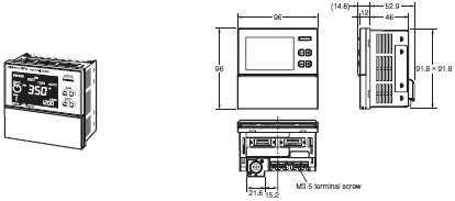
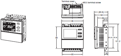
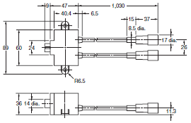
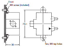
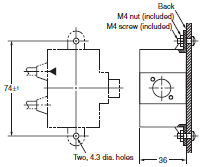
OMRON H8PS dimension
H8PS Cam Positioner/Dimensionslast update: March 10, 2015
Main Unit
Cam Positioners
Flush Mounting Models
H8PS-8B[] (8-output Models)
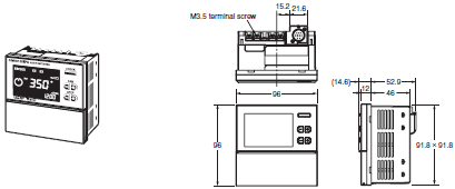
H8PS-16B[] (16-output Models)
H8PS-32B[] (32-output Models)
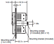
Panel Cutout (according to DIN 43700)

Note: Mounting panel thickness must be 1 to 5 mm.
Flush mounting
Note: An 8-output Model is shown in the above diagrams. The Encoder is connected from the bottom with 16-/32-output
Models.
Surface Mounting Models
H8PS-8BF[] (8-output Models)
H8PS-16BF[] (16-output Models)
H8PS-32BF[] (32-output Models)
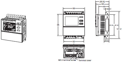
Mounting holes
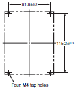
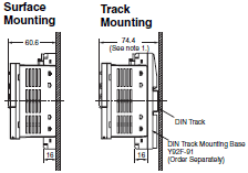
Note: 1. These dimensions vary with the kind of DIN track (reference value).
2. An 8-output Model is shown in the above diagrams. The Encoder is connected from the bottom with 16-/32-
output Models.
Accessories (Order Separately)
Parallel Input Adapters
Y92C-30
This Adapter enables two H8PS Cam Positioners to share signals from an Encoder.
Note: H8PS has been improved in 2004 April.
Do not mix old and new model with Y92C-30.
When you use 2 x H8PS, please use by "Old & Old" or "New & New" models.
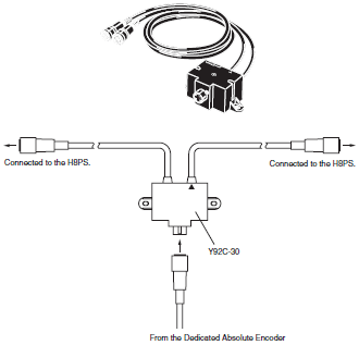
Use the cable marked with a triangle when connecting only one H8PS Cam Positioner to the Parallel Input Adapter.
Panel Surface Mounting
Panel Back Mounting
Watertight Cover
Y92A-96N
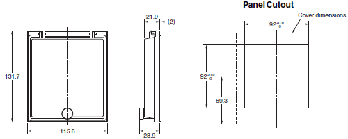
Use for flush mounting when waterproofing is required. The Y96A-96N conforms to IP66 and NEMA4 (for indoor use) standards for waterproofing.
The operating environment may cause the waterproof packing to deteriorate, shrink, or harden.
Therefore, it is recommended that the packing be replaced regularly.
Mounting Track
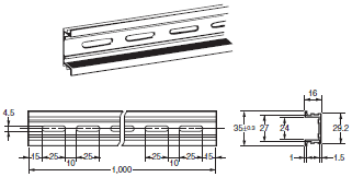
PFP-100N
PFP-50N
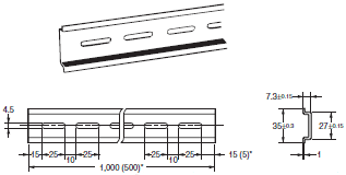
* The numbers in parentheses () are dimensions for the PFP-50N.
PFP-100N2
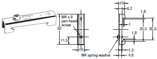
End Plate
PFP-M
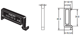
Spacer
PFP-S
last update: March 10, 2015
OMRON H8PS catalog
H8PS Cam Positioner/Catalog- Catalog
- Manual
- CAD
English
Global Edition
| Catalog Name | Catalog Number [size] | Last Update | |
|---|---|---|---|
| | - [5259KB] | Oct 28, 201520151028 | H8PS Data Sheet |
OMRON H8PS lineup
H8PS Cam Positioner/Lineuplast update: April 01, 2014
Cam Positioner
| Number of outputs | Mounting method | Output configuration | Bank function | Model |
|---|---|---|---|---|
| 8 outputs | Flush mounting | NPN transistor output | No | H8PS-8B |
| PNP transistor output | H8PS-8BP | |||
| Surface mounting/ track mounting | NPN transistor output | H8PS-8BF | ||
| PNP transistor output | H8PS-8BFP | |||
| 16 outputs | Flush mounting | NPN transistor output | Yes | H8PS-16B |
| PNP transistor output | H8PS-16BP | |||
| Surface mounting/ track mounting | NPN transistor output | H8PS-16BF | ||
| PNP transistor output | H8PS-16BFP | |||
| 32 outputs | Flush mounting | NPN transistor output | H8PS-32B | |
| PNP transistor output | H8PS-32BP | |||
| Surface mounting/ track mounting | NPN transistor output | H8PS-32BF | ||
| PNP transistor output | H8PS-32BFP |
Dedicated Absolute Encoder
| Type | Resolution | Cable length | Model |
|---|---|---|---|
| Economy | 256 | 2 m | E6CP-AG5C-C 256P/R 2M |
| Standard | 256 | 1 m | E6C3-AG5C-C 256P/R 1M |
| 2 m | E6C3-AG5C-C 256P/R 2M | ||
| 360 | E6C3-AG5C-C 360P/R 2M | ||
| 720 | E6C3-AG5C-C 720P/R 2M | ||
| Rigid | 256 | 2 m | E6F-AG5C-C 256P/R 2M |
| 360 | E6F-AG5C-C 360P/R 2M | ||
| 720 | E6F-AG5C-C 720P/R 2M |
Accessories (Order Separately)
| Name | Specification | Model |
|---|---|---|
| Discrete Wire Output Cable | 2 m | Y92S-41-200 |
| Connector-type Output Cable | 2 m | E5ZE-CBL200 |
| Support Software | CD-ROM | H8PS-SOFT-V1 |
| Shaft Coupling for the E6CP | Axis: 6 mm dia. | E69-C06B |
| Shaft Coupling for the E6C3 | Axis: 8 mm dia. | E69-C08B |
| Shaft Coupling for the E6F | Axis: 10 mm dia. | E69-C10B |
| Extension Cable (See note.) | 5 m (same for E6CP, E6C3, and E6F) | E69-DF5 |
| Parallel Input Adapter | Two Units can operate in parallel. | Y92C-30 |
| Protective Cover | --- | Y92A-96B |
| Watertight Cover | --- | Y92A-96N |
| Track Mounting Base | --- | Y92F-91 |
| Mounting Track | 50 cm × 7.3 mm (l × t) | PFP-50N |
| 1 m × 7.3 mm (l × t) | PFP-100N | |
| 1 m × 16 mm (l × t) | PFP-100N2 | |
| End Plate | --- | PFP-M |
| Spacer | --- | PFP-S |
Note: Ask your OMRON representative about the availability of non-standard lengths.
Recommended USB Cables
| Name | Recommended manufacturer | Specification | Model |
|---|---|---|---|
| USB Cable | ELECOM CO.Ltd. | A-miniB, 2m | U2C-MF20BK |
Note: If you can't purchase recommended replacement, please purchase commercially available USB cable that attached
ferrite core.
last update: April 01, 2014
- NO. H8PS
- TYPE:Cam Positioners Copyright Statement Copyright Statement
- DATE:2021-06-07
- Associated products:
G3ZA Multi-channel Power Controller/Features 3F88L-160 / 162 Cam Positioner/Features