
OMRON E3JK (NEW)Sensors/ Photoelectric Sensors/Built-in Power Supply
OMRON E3JK (NEW) Sensors
- E3JK (NEW) Built-in Power Supply Photoelectric Sensor/Specifications
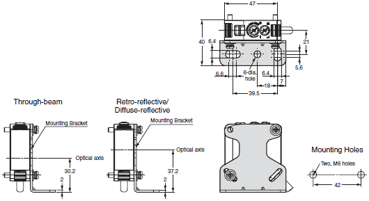
- E3JK (NEW) Built-in Power Supply Photoelectric Sensor/Dimensions
- E3JK (NEW) Built-in Power Supply Photoelectric Sensor/Lineup
- E3JK (NEW) Built-in Power Supply Photoelectric Sensor/Catalog
- Purchase the OMRON E3JK (NEW) Built-in Power Supply
OMRON E3JK (NEW) Dimensions
/Images/l_3179-25-169777-198x198.jpglast update: May 11, 2015
• Long sensing distance that is approximately 8 times that of our conventional model (for the Through-beam and Diffuse-reflective models).
(Through-beam: 40 m, Retro-reflective: 7 m, and Diffuse-reflective: 2.5 m.)
• Improved visibility:
• A red LED that makes the spot visible.
• Large indicators that can be seen even from a distance.
• Improved operability.
(Enlarged sensitivity adjuster and operation selector)
• Freely selectable power supply input (24 to 240 VDC, 24 to 240 VAC).
(Additional types added to the DC type lineup.)
• Models with infrared LEDs are also available.
last update: May 11, 2015
Purchase the OMRON Built-in Power Supply Please fill in the following
If you have just landed here, this product OMRON E3JK (NEW) Sensors,Sensors is offered online by Tianin FLD Technical Co.,Ltd. This is an online store providing Sensors at wholesale prices for consumers. You can call us or send enquiry, we would give you the prices, packing,deliverty and more detailed information on the E3JK (NEW) We cooperate with DHL,TNT,FEDEX,UPS,EMS,etc.They guarantee to meet your needs in terms of time and money,even if you need your OMRON E3JK (NEW)Sensors tomorrow morning (aka overnight or next day air) on your desk, 2, 3 days or more.Note to international customers, YES, we ship worldwide.
ZN-A Air Clean Units/Features
E5AR Digital Controller/Features
CK3W-AX1414[] / 1515[] CK3W Axial Interface Unit/Features
CS1W-EIP21 CS-series EtherNet/IP Unit/Features
XS5 Round Water-resistant Connectors (M12 Smartclick)/Features
OMRON E3JK (NEW) specification
E3JK (NEW) Built-in Power Supply Photoelectric Sensor/Specificationslast update: October 28, 2015
| Sensing method | Through-beam | ||||
|---|---|---|---|---|---|
| Model | E3JK-TR11-[] | E3JK-TR12-[] | E3JK-TR13-[] | E3JK-TR14-[] | |
| Sensing distance | 40 m | 5 m | 40 m | 5 m | |
| Standard sensing object | Opaque: 17-mm dia. min. | ||||
| Differential travel | - | ||||
| Directional angle | Both Emitter and Receiver 3° min. | ||||
| Light source (wavelength) | Red LED (624 nm) | Infrared LED (850 nm) | |||
| Power supply voltage | 24 to 240 VDC ±10%, ripple (p-p): 10% max. 24 to 240 VAC ±10%, 50/60 Hz | ||||
| Power consumption | DC | 3 W max. (Emitter 1.5 W max. Receiver 1.5 W max.) | |||
| AC | 3 W max. (Emitter 1.5 W max. Receiver 1.5 W max.) | ||||
| Control output | Relay output SPDT, 250 VAC, 3 A max. (cosϕ= 1), 5 VDC, 10 mA min., Light-ON/Dark-ON selectable | ||||
| Protection circuits | - | ||||
| Life expectancy (relay output) | Mechanical | 50,000,000 times min. (switching frequency: 18,000 times/h) | |||
| Electrical | 100,000 times min. (switching frequency: 1,800 times/h) | ||||
| Response time | 20 ms max. | ||||
| Sensitivity adjustment | One-turn adjuster Receiver (E3JK-TR1[]-D) only | ||||
| Ambient illumination (Receiver side) | Incandescent lamp: 3,000 lx max., Sunlight: 11,000 lx max. | ||||
| Ambient temperature range | Operating: -25°C to 55°C, Storage: -40°C to 70°C (with no icing or condensation) | ||||
| Ambient humidity range | Operating: 35% to 85%, Storage: 35% to 95% (with no condensation) | ||||
| Insulation resistance | 20 MΩ min. at 500 VDC | ||||
| Dielectric strength | 1,500 VAC, 50/60 Hz for 1 min | ||||
| Vibration resistance | Destruction | 10 to 55 Hz with a 1.5 mm double amplitude for 2 hours each in X, Y, and Z directions | |||
| Malfunction | 10 to 55 Hz with a 1.5 mm double amplitude for 2 hours each in X, Y, and Z directions | ||||
| Shock resistance | Destruction | 500 m/s2 for 3 times each in X, Y, and Z directions | |||
| Malfunction | 100 m/s2 for 3 times each in X, Y, and Z directions | ||||
| Degree of protection | IEC 60529 IP64 | ||||
| Connection method | Pre-wired (standard length: 2 m) | ||||
| Weight (packed state) | Approx. 350 g | ||||
| Material | Case | ABS (Acrylonitrile Butadiene Styrene) | |||
| Lens/Display window | Methacrylic resin | ||||
| Adjuster | POM | ||||
| Cable | PVC | ||||
| Bending radius of cable | R18 | ||||
| Accessories | Instruction manual and Mounting Bracket (E3JK-TR1[]-C only) | ||||
| Sensing method | Retro-reflective (without MSR function) | Retro-reflective (with MSR function) | ||
|---|---|---|---|---|
| Model | E3JK-RR11-[] | E3JK-RR13-[] | E3JK-RR12-[] | |
| Sensing distance | 7 m [100 mm]* (When using E39-R1), 11 m [100 mm]* (When using E39-R2) | 6 m [100 mm]* (When using E39-R1), 10 m [100 mm]* (When using E39-R2) | ||
| Standard sensing object | Opaque: 75-mm dia. min. (When using E39-R1), Opaque: 100-mm dia. min. (When using E39-R2) | |||
| Differential travel | - | |||
| Directional angle | 1.5° min. | |||
| Light source (wavelength) | Red LED (624 nm) | Infrared LED (850 nm) | Red LED (624 nm) | |
| Power supply voltage | 24 to 240 VDC ±10%, ripple (p-p): 10% max. 24 to 240 VAC ±10%, 50/60 Hz | |||
| Power consumption | DC | 2 W max. | ||
| AC | 2 W max. | |||
| Control output | Relay output SPDT, 250 VAC, 3 A max. (cosϕ= 1), 5 VDC, 10 mA min., Light-ON/Dark-ON selectable | |||
| Protection circuits | Mutual interference prevention function | |||
| Life expectancy (relay output) | Mechanical | 50,000,000 times min. (switching frequency: 18,000 times/h) | ||
| Electrical | 100,000 times min. (switching frequency: 1,800 times/h) | |||
| Response time | 20 ms max. | |||
| Sensitivity adjustment | One-turn adjuster | |||
| Ambient illumination (Receiver side) | Incandescent lamp: 3,000 lx max., Sunlight: 11,000 lx max. | |||
| Ambient temperature range | Operating: -25°C to 55°C, Storage: -40°C to 70°C (with no icing or condensation) | |||
| Ambient humidity range | Operating: 35% to 85%, Storage: 35% to 95% (with no condensation) | |||
| Insulation resistance | 20 MΩ min. at 500 VDC | |||
| Dielectric strength | 1,500 VAC, 50/60 Hz for 1 min | |||
| Vibration resistance | Destruction | 10 to 55 Hz with a 1.5 mm double amplitude for 2 hours each in X, Y, and Z directions | ||
| Malfunction | 10 to 55 Hz with a 1.5 mm double amplitude for 2 hours each in X, Y, and Z directions | |||
| Shock resistance | Destruction | 500 m/s2 for 3 times each in X, Y, and Z directions | ||
| Malfunction | 100 m/s2 for 3 times each in X, Y, and Z directions | |||
| Degree of protection | IEC 60529 IP64 | |||
| Connection method | Pre-wired (standard length: 2 m) | |||
| Weight (packed state) | Approx. 180 g | |||
| Material | Case | ABS (Acrylonitrile Butadiene Styrene) | ||
| Lens/Display window | Methacrylic resin | |||
| Adjuster | POM | |||
| Cable | PVC | |||
| Bending radius of cable | R18 | |||
| Accessories | Instruction manual, Mounting Bracket (E3JK-RR1[]-C only), and Reflector (E3JK- RR1[]-C only) | |||
*Values in parentheses indicate the minimum required distances between the Sensors and Reflectors.
| Sensing method | Diffuse-reflective | ||||
|---|---|---|---|---|---|
| Model | E3JK-DR11-[] | E3JK-DR12-[] | E3JK-DR13-[] | E3JK-DR14-[] | |
| Sensing distance | White paper (300 × 300 mm): 2.5 m | White paper (100 × 100 mm): 300 mm | White paper (300 × 300 mm): 2.5 m | White paper (100 × 100 mm): 300 mm | |
| Standard sensing object | - | ||||
| Differential travel | 20% max. of sensing distance | ||||
| Directional angle | - | ||||
| Light source (wavelength) | Red LED (624 nm) | Infrared LED (850 nm) | |||
| Power supply voltage | 24 to 240 VDC ±10%, ripple (p-p): 10% max. 24 to 240 VAC ±10%, 50/60 Hz | ||||
| Power consumption | DC | 2 W max. | |||
| AC | 2 W max. | ||||
| Control output | Relay output SPDT, 250 VAC, 3 A max. (cosϕ= 1), 5 VDC, 10 mA min., Light-ON/Dark-ON selectable | ||||
| Protection circuits | Mutual interference prevention function | ||||
| Life expectancy (relay output) | Mechanical | 50,000,000 times min. (switching frequency: 18,000 times/h) | |||
| Electrical | 100,000 times min. (switching frequency: 1,800 times/h) | ||||
| Response time | 20 ms max. | ||||
| Sensitivity adjustment | One-turn adjuster | ||||
| Ambient illumination (Receiver side) | Incandescent lamp: 3,000 lx max., Sunlight: 11,000 lx max. | ||||
| Ambient temperature range | Operating: -25°C to 55°C, Storage: -40°C to 70°C (with no icing or condensation) | ||||
| Ambient humidity range | Operating: 35% to 85%, Storage: 35% to 95% (with no condensation) | ||||
| Insulation resistance | 20 MΩ min. at 500 VDC | ||||
| Dielectric strength | 1,500 VAC, 50/60 Hz for 1 min | ||||
| Vibration resistance | Destruction | 10 to 55 Hz with a 1.5 mm double amplitude for 2 hours each in X, Y, and Z directions | |||
| Malfunction | 10 to 55 Hz with a 1.5 mm double amplitude for 2 hours each in X, Y, and Z directions | ||||
| Shock resistance | Destruction | 500 m/s2 for 3 times each in X, Y, and Z directions | |||
| Malfunction | 100 m/s2 for 3 times each in X, Y, and Z directions | ||||
| Degree of protection | IEC 60529 IP64 | ||||
| Connection method | Pre-wired (standard length: 2 m) | ||||
| Weight (packed state) | Approx. 180 g | ||||
| Material | Case | ABS (Acrylonitrile Butadiene Styrene) | |||
| Lens/Display window | Methacrylic resin | ||||
| Adjuster | POM | ||||
| Cable | PVC | ||||
| Bending radius of cable | R18 | ||||
| Accessories | Instruction manual and Mounting Bracket (E3JK-DR1[]-C only) | ||||
| Sensing method | Through-beam | ||||
|---|---|---|---|---|---|
| Model | NPN output | E3JK-TN11 | E3JK-TN12 | E3JK-TN13 | E3JK-TN14 |
| PNP output | E3JK-TP11 | E3JK-TP12 | E3JK-TP13 | E3JK-TP14 | |
| Sensing distance | 40 m | 5 m | 40 m | 5 m | |
| Standard sensing object | Opaque: 17-mm dia. min. | ||||
| Differential travel | - | ||||
| Directional angle | Both Emitter and Receiver 3° min. | ||||
| Light source (wavelength) | Red LED (624 nm) | Infrared LED (850 nm) | |||
| Power supply voltage | 10 to 30 VDC, including ripple (p-p): 10% | ||||
| Power consumption | DC | 40 mA max. (Emitter 25 mA max. Receiver 15 mA max.) | |||
| AC | - | ||||
| Control output | Load power supply voltage: 30 V max., Load current: 100 mA max., Residual voltage: 3 V max., open-collector output (NPN/PNP output depending on model), Light-ON/Dark-ON selectable | ||||
| Protection circuits | Power supply reverse polarity protection, Output short-circuit protection, and Output reverse polarity protection | ||||
| Life expectancy (relay output) | Mechanical | - | |||
| Electrical | - | ||||
| Response time | 1 ms max. | ||||
| Sensitivity adjustment | One-turn adjuster Receiver (E3JK-T[][][]-D) only | ||||
| Ambient illumination (Receiver side) | Incandescent lamp: 3,000 lx max., Sunlight: 11,000 lx max. | ||||
| Ambient temperature range | Operating: -25°C to 55°C, Storage: -40°C to 70°C (with no icing or condensation) | ||||
| Ambient humidity range | Operating: 35% to 85%, Storage: 35% to 95% (with no condensation) | ||||
| Insulation resistance | 20 MΩ min. at 500 VDC | ||||
| Dielectric strength | 1,500 VAC, 50/60 Hz for 1 min | ||||
| Vibration resistance | Destruction | 10 to 55 Hz with a 1.5 mm double amplitude for 2 hours each in X, Y, and Z directions | |||
| Malfunction | 10 to 55 Hz with a 1.5 mm double amplitude for 2 hours each in X, Y, and Z directions | ||||
| Shock resistance | Destruction | 500 m/s2 for 3 times each in X, Y, and Z directions | |||
| Malfunction | 500 m/s2 for 3 times each in X, Y, and Z directions | ||||
| Degree of protection | IEC 60529 IP64 | ||||
| Connection method | Pre-wired (standard length: 2 m) | ||||
| Weight (packed state) | Approx. 300 g | ||||
| Material | Case | ABS (Acrylonitrile Butadiene Styrene) | |||
| Lens/Display window | Methacrylic resin | ||||
| Adjuster | POM | ||||
| Cable | PVC | ||||
| Bending radius of cable | R18 | ||||
| Accessories | Instruction manual | ||||
| Sensing method | Retro-reflective (without MSR function) | Retro-reflective (with MSR function) | ||
|---|---|---|---|---|
| Model | NPN output | E3JK-RN11 | E3JK-RN13 | E3JK-RN12 |
| PNP output | E3JK-RP11 | E3JK-RP13 | E3JK-RP12 | |
| Sensing distance | 7 m [100 mm]* (When using E39-R1), 11 m [100 mm]* (When using E39-R2) | 6 m [100 mm]* (When using E39-R1), 10 m [100 mm]* (When using E39-R2) | ||
| Standard sensing object | Opaque: 75-mm dia. min. | |||
| Differential travel | - | |||
| Directional angle | 1.5° min. | |||
| Light source (wavelength) | Red LED (624 nm) | Infrared LED (850 nm) | Red LED (624 nm) | |
| Power supply voltage | 10 to 30 VDC, including ripple (p-p): 10% | |||
| Power consumption | DC | 30 mA max. | ||
| AC | - | |||
| Control output | Load power supply voltage: 30 V max., Load current: 100 mA max., Residual voltage: 3 V max., opencollector output (NPN/PNP output depending on model), Light-ON/Dark-ON selectable | |||
| Protection circuits | Power supply reverse polarity protection, Output short-circuit protection, Mutual interference prevention function, and Output reverse polarity protection | |||
| Life expectancy (relay output) | Mechanical | - | ||
| Electrical | - | |||
| Response time | 1 ms max. | |||
| Sensitivity adjustment | One-turn adjuster | |||
| Ambient illumination (Receiver side) | Incandescent lamp: 3,000 lx max., Sunlight: 11,000 lx max. | |||
| Ambient temperature range | Operating: -25°C to 55°C, Storage: -40°C to 70°C (with no icing or condensation) | |||
| Ambient humidity range | Operating: 35% to 85%, Storage: 35% to 95% (with no condensation) | |||
| Insulation resistance | 20 MΩ min. at 500 VDC | |||
| Dielectric strength | 1,500 VAC, 50/60 Hz for 1 min | |||
| Vibration resistance | Destruction | 10 to 55 Hz with a 1.5 mm double amplitude for 2 hours each in X, Y, and Z directions | ||
| Malfunction | 10 to 55 Hz with a 1.5 mm double amplitude for 2 hours each in X, Y, and Z directions | |||
| Shock resistance | Destruction | 500 m/s2 for 3 times each in X, Y, and Z directions | ||
| Malfunction | 500 m/s2 for 3 times each in X, Y, and Z directions | |||
| Degree of protection | IEC 60529 IP64 | |||
| Connection method | Pre-wired (standard length: 2 m) | |||
| Weight (packed state) | Approx. 160 g | |||
| Material | Case | ABS (Acrylonitrile Butadiene Styrene) | ||
| Lens/Display window | Methacrylic resin | |||
| Adjuster | POM | |||
| Cable | PVC | |||
| Bending radius of cable | R18 | |||
| Accessories | Instruction manual | |||
*Values in parentheses indicate the minimum required distances between the Sensors and Reflectors.
| Sensing method | Diffuse-reflective | ||||
|---|---|---|---|---|---|
| Model | NPN output | E3JK-DN11 | E3JK-DN12 | E3JK-DN13 | E3JK-DN14 |
| PNP output | E3JK-DP11 | E3JK-DP12 | E3JK-DP13 | E3JK-DP14 | |
| Sensing distance | White paper (300 × 300 mm): 2.5 m | White paper (100 × 100 mm): 300 mm | White paper (300 × 300 mm): 2.5 m | White paper (100 × 100 mm): 300 mm | |
| Standard sensing object | - | ||||
| Differential travel | 20% max. of sensing distance | ||||
| Directional angle | - | ||||
| Light source (wavelength) | Red LED (624 nm) | Infrared LED (850 nm) | |||
| Power supply voltage | 10 to 30 VDC, including ripple (p-p): 10% | ||||
| Power consumption | DC | 30 mA max. | |||
| AC | - | ||||
| Control output | Load power supply voltage: 30 V max., Load current: 100 mA max., Residual voltage: 3 V max., opencollector output (NPN/PNP output depending on model), Light-ON/Dark-ON selectable | ||||
| Protection circuits | Power supply reverse polarity protection, Output short-circuit protection, Mutual interference prevention function, and Output reverse polarity protection | ||||
| Life expectancy (relay output) | Mechanical | - | |||
| Electrical | - | ||||
| Response time | 1 ms max. | ||||
| Sensitivity adjustment | One-turn adjuster | ||||
| Ambient illumination (Receiver side) | Incandescent lamp: 3,000 lx max., Sunlight: 11,000 lx max. | ||||
| Ambient temperature range | Operating: -25°C to 55°C, Storage: -40°C to 70°C (with no icing or condensation) | ||||
| Ambient humidity range | Operating: 35% to 85%, Storage: 35% to 95% (with no condensation) | ||||
| Insulation resistance | 20 MΩ min. at 500 VDC | ||||
| Dielectric strength | 1,500 VAC, 50/60 Hz for 1 min | ||||
| Vibration resistance | Destruction | 10 to 55 Hz with a 1.5 mm double amplitude for 2 hours each in X, Y, and Z directions | |||
| Malfunction | 10 to 55 Hz with a 1.5 mm double amplitude for 2 hours each in X, Y, and Z directions | ||||
| Shock resistance | Destruction | 500 m/s2 for 3 times each in X, Y, and Z directions | |||
| Malfunction | 500 m/s2 for 3 times each in X, Y, and Z directions | ||||
| Degree of protection | IEC 60529 IP64 | ||||
| Connection method | Pre-wired (standard length: 2 m) | ||||
| Weight (packed state) | Approx. 160 g | ||||
| Material | Case | ABS (Acrylonitrile Butadiene Styrene) | |||
| Lens/Display window | Methacrylic resin | ||||
| Adjuster | POM | ||||
| Cable | PVC | ||||
| Bending radius of cable | R18 | ||||
| Accessories | Instruction manual | ||||
last update: October 28, 2015
OMRON E3JK (NEW) dimension
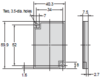
E3JK (NEW) Built-in Power Supply Photoelectric Sensor/Dimensionslast update: May 11, 2015
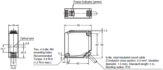
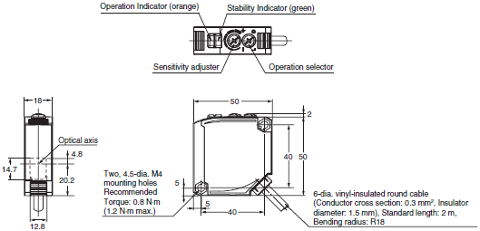
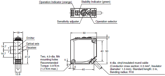
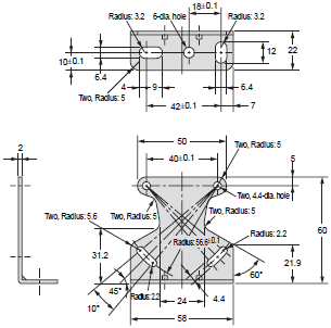
Tolerance class IT16 applies to dimensions in this datasheet unless otherwise specified.
Sensors
Through-beam
E3JK-T[]1[]
<Emitter>
E3JK-T[]1[]-L
<Receiver>
E3JK-T[]1[]-D
Retro-reflective/Diffuse-reflective
E3JK-R[]1[]
E3JK-D[]1[]
Accessories
Mounting Bracket (Order separately)
Mounting Bracket
E39-L40
With Mounting Bracket Attached
Reflector (Order separately)
E39-R1
E39-R1S
Material:
Reflective surface: acrylic
Rear surface: ABS
E39-R2

Material:
Reflective surface: acrylic
Rear surface: ABS
last update: May 11, 2015
OMRON E3JK (NEW) lineup
E3JK (NEW) Built-in Power Supply Photoelectric Sensor/Lineuplast update: May 11, 2015
Sensors
Sensors without Brackets or Reflectors
| Power supply voltage | Sensing method | Appearance | Sensing distance | Output configuration | Model |
|---|---|---|---|---|---|
| AC/DC power supply selectable type | Through- beam *1 (Emitter + Receiver) |  | 40 m (Red light) | Relay | E3JK-TR11 2M Emitter: E3JK-TR11-L 2M Receiver: E3JK-TR11-D 2M |
| 5 m (Red light) | E3JK-TR12 2M Emitter: E3JK-TR12-L 2M Receiver: E3JK-TR12-D 2M | ||||
| 40 m (Infrared light) | E3JK-TR13 2M Emitter: E3JK-TR13-L 2M Receiver: E3JK-TR13-D 2M | ||||
| 5 m (Infrared light) | E3JK-TR14 2M Emitter: E3JK-TR14-L 2M Receiver: E3JK-TR14-D 2M | ||||
| Retro- reflective without MSR function |  *2 *2 | *3 7 m [100 mm] (When using E39-R1) (Red light) 11 m [100 mm] (When using E39-R2) (Red light) | E3JK-RR11 2M | ||
| *3 7 m [100 mm] (When using E39-R1) (Infrared light) 11 m [100 mm] (When using E39-R2) (Infrared light) | E3JK-RR13 2M | ||||
| Retro- reflective with MSR function | *3 6 m [100 mm] (When using E39-R1) (Red light) 10 m [100 mm] (When using E39-R2) (Red light) | E3JK-RR12 2M | |||
| Diffuse- reflective |  | 2.5 m (Red light) | E3JK-DR11 2M | ||
| 300 mm (Red light) | E3JK-DR12 2M | ||||
| 2.5 m (Infrared light) | E3JK-DR13 2M | ||||
| 300 mm (Infrared light) | E3JK-DR14 2M |
*1. Through-beam Sensors are sold in sets that include both the Emitter and Receiver.
*2. A Reflector is not included. Purchase a Reflector separately to match the intended use of the Sensor.
*3. Values in parentheses indicate the minimum required distances between the Sensors and Reflectors.
| Power supply voltage | Sensin method | Appearance | Sensing distance | Output configuration | Model |
|---|---|---|---|---|---|
| DC | Through- beam *1 (Emitter + Receiver) |  | 40 m (Red light) | NPN | E3JK-TN11 2M Emitter: E3JK-TN11-L 2M Receiver: E3JK-TN11-D 2M |
| PNP | E3JK-TP11 2M Emitter: E3JK-TP11-L 2M Receiver: E3JK-TP11-D 2M | ||||
| 5 m (Red light) | NPN | E3JK-TN12 2M Emitter: E3JK-TN12-L 2M Receiver: E3JK-TN12-D 2M | |||
| PNP | E3JK-TP12 2M Emitter: E3JK-TP12-L 2M Receiver: E3JK-TP12-D 2M | ||||
| 40 m (Infrared light) | NPN | E3JK-TN13 2M Emitter: E3JK-TN13-L 2M Receiver: E3JK-TN13-D 2M | |||
| PNP | E3JK-TP13 2M Emitter: E3JK-TP13-L 2M Receiver: E3JK-TP13-D 2M | ||||
| 5 m (Infrared light) | NPN | E3JK-TN14 2M Emitter: E3JK-TN14-L 2M Receiver: E3JK-TN14-D 2M | |||
| PNP | E3JK-TP14 2M Emitter: E3JK-TP14-L 2M Receiver: E3JK-TP14-D 2M | ||||
| Retro- reflective without MSR function |  *2 *2 | *3 7 m [100 mm] (When using E39-R1) (Red light) 11 m [100 mm] (When using E39-R2) (Red light) | NPN | E3JK-RN11 2M | |
| PNP | E3JK-RP11 2M | ||||
| *3 7 m [100 mm] (When using E39-R1) (Infrared light) 11 m [100 mm] (When using E39-R2) (Infrared light) | NPN | E3JK-RN13 2M | |||
| PNP | E3JK-RP13 2M | ||||
| Retro- reflective with MSR function | *3 6 m [100 mm] (When using E39-R1) (Red light) 10 m [100 mm] (When using E39-R2) (Red light) | NPN | E3JK-RN12 2M | ||
| PNP | E3JK-RP12 2M | ||||
| Diffuse- reflective |  | 2.5 m (Red light) | NPN | E3JK-DN11 2M | |
| PNP | E3JK-DP11 2M | ||||
| 300 mm (Red light) | NPN | E3JK-DN12 2M | |||
| PNP | E3JK-DP12 2M | ||||
| 2.5 m (Infrared light) | NPN | E3JK-DN13 2M | |||
| PNP | E3JK-DP13 2M | ||||
| 300 mm (Infrared light) | NPN | E3JK-DN14 2M | |||
| PNP | E3JK-DP14 2M |
*1. Through-beam Sensors are sold in sets that include both the Emitter and Receiver.
*2. A Reflector is not included. Purchase a Reflector separately to match the intended use of the Sensor.
*3. Values in parentheses indicate the minimum required distances between the Sensors and Reflectors.
Sensors with Brackets and Reflectors (The model numbers contain ("-C.")
| Power supply voltage | Sensing method | Appearance | Sensing distance | Output configuration | Model |
|---|---|---|---|---|---|
| AC/DC power supply selectable type | Through- beam *1 (Emitter + Receiver) |  | 40 m (Red light) | Relay | E3JK-TR11-C 2M Emitter: E3JK-TR11-L 2M Receiver: E3JK-TR11-D 2M |
| 5 m (Red light) | E3JK-TR12-C 2M Emitter: E3JK-TR12-L 2M Receiver: E3JK-TR12-D 2M | ||||
| 40 m (Infrared light) | E3JK-TR13-C 2M Emitter: E3JK-TR13-L 2M Receiver: E3JK-TR13-D 2M | ||||
| 5 m (Infrared light) | E3JK-TR14-C 2M Emitter: E3JK-TR14-L 2M Receiver: E3JK-TR14-D 2M | ||||
| Retro- reflective without MSR function |  | *2 7 m [100 mm] (When using E39-R1) (Red light) 11 m [100 mm] (When using E39-R2) (Red light) | E3JK-RR11-C 2M | ||
| *2 7 m [100 mm] (When using E39-R1) (Infrared light) 11 m [100 mm] (When using E39-R2) (Infrared light) | E3JK-RR13-C 2M | ||||
| Retro- reflective with MSR function | *2 6 m [100 mm] (When using E39-R1) (Red light) 10 m [100 mm] (When using E39-R2) (Red light) | E3JK-RR12-C 2M | |||
| Diffuse- reflective |  | 2.5 m (Red light) | E3JK-DR11-C 2M | ||
| 300 mm (Red light) | E3JK-DR12-C 2M | ||||
| 2.5 m (Infrared light) | E3JK-DR13-C 2M | ||||
| 300 mm (Infrared light) | E3JK-DR14-C 2M |
*1. Through-beam Sensors are sold in sets that include both the Emitter and Receiver.
*2. Values in parentheses indicate the minimum required distances between the Sensors and Reflectors.
Accessories (Order Separately)
Reflectors (A Reflector is required for each Retro-reflective Sensor.)
The E39-R1 is enclosed with Sensors with model numbers that contain "-C."
| Name | Sensing distance (rated value) | Model | Quantity | |
|---|---|---|---|---|
| Reflectors | E3JK-R[]11 | 7 m [100 mm] * | E39-R1 | 1 |
| E3JK-R[]12 | 6 m [100 mm] * | |||
| E3JK-R[]13 | 7 m [100 mm] * | |||
| E3JK-R[]11 | 9 m [100 mm] * | E39-R1S | 1 | |
| E3JK-R[]12 | 7 m [100 mm] * | |||
| E3JK-R[]13 | 9 m [100 mm] * | |||
| E3JK-R[]11 | 11 m [100 mm] * | E39-R2 | 1 | |
| E3JK-R[]12 | 10 m [100 mm] * | |||
| E3JK-R[]13 | 11 m [100 mm] * | |||
Note: Refer to Engineering Data on Catalog for details.
* Values in parentheses indicate the minimum required distances between the Sensors and Reflectors.
Mounting Bracket
A Mounting Bracket is enclosed with Sensors with model numbers that contain "-C."
| Appearance | Model | Quantity |
|---|---|---|
 | E39-L40 | 1 |
Note: 1. When using a Through-beam Sensor, order one Mounting Bracket for the Receiver and one for the Emitter.
2. For details, refer to Mounting Brackets on E39-L/E39-S/E39-R which can be accessed from your OMRON website.
last update: May 11, 2015
OMRON E3JK (NEW) catalog
E3JK (NEW) Built-in Power Supply Photoelectric Sensor/Catalog- Catalog
- Manual
- CAD
English
Global Edition
| Catalog Name | Catalog Number [size] | Last Update | |
|---|---|---|---|
| | E432-E1-03 [6206KB] | Oct 28, 201520151028 | E3JK (NEW) Data Sheet |
- NO. E3JK (NEW)
- TYPE:Photoelectric Sensors Built-in Power Supply
 Copyright Statement
 - DATE:2021-06-14
- Associated products:
E3FC Photoelectric sensors in M18 stainless steel housing/Features E3JM Built-in Power Supply Photoelectric Sensor/Features